Coatings for Bipolar Plates of Proton Exchange Membrane Fuel Cells and Electrolyzers Lifetime improvement and cost reduction of bipolar plates by realizing a good corrosion resistance and a low interfacial contact resistance
IHI Ionbond and IHI Hauzer
Demand for fuel cells and electrolyzers is increasing toward decarbonization. We will introduce the coating technologies for bipolar plates which form the electrochemical cells in fuel cells and electrolyzers, and the efforts that IHI Ionbond and IHI Hauzer are making to reduce the cost and extend the life of fuel cells and electrolyzers.
HURKMANS Ton SCHUIVENS Frank VAN DER KOLK Gerry UMMELS Joris IHI Ionbond AG
BOSCH Roel FUCHIGAMI Kenji JACOBS Ruud IHI Hauzer Techno Coating B. V.
Fuel cell and bipolar plate
Hydrogen gas can be formed using solar or wind energy and is then called green hydrogen. In general, green hydrogen is generated in an electrolyzer with renewable energy. It can be stored relatively easily, and transport over longer distances is also possible. Hydrogen can be used to generate heat or energy emitting only water vapor, it has a near zero CO2 emission. It is expected that green hydrogen will be generated in big volumes at locations where the production is cost effective with rich renewable energy resources, such as off-shore wind-mill parks and solar farms in areas near the meridian. Plans for that are already very substantial. In a fuel cell (FC) hydrogen reacts with oxygen to form electric energy and emits water vapor only. FCs will be commonly employed for various transport systems. FC powered trains and buses are already in operation, and FC powered trucks are in development. Among various kinds of FCs, the polymer-electrolyte-membrane-fuel cell (PEMFC) has already been developed in the sixties, with first application in the spaceflight project Gemini. The PEMFC has distinct advantages over other hydrogen generating technologies. The mass is relatively low, there are no aggressive chemicals used, and the power has a large dynamic range. Therefore, it is expected that firstly the automotive industry will apply PEMFC technology for long distance applications and possibly later the aero industry. The expectation is that by 2030 between 5% and 20% of cars will be powered by FCs.
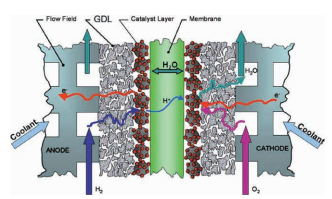
The FC is schematically shown in the figure (Owejan et al., DOI:10.1016/J.IJHYDENE.2008.12.100). It consists of a pair of bipolar plates (BPPs), an interlayer called the gas diffusion layer (GDL), catalyst layer and a membrane. At the figure is the anode portion of the BPP where hydrogen is fed into the FC. At the platinum containing catalyst layer hydrogen molecules are split and ionized to form hydrogen ions. Hydrogen ions can diffuse through the membrane to the cathode side. The electrons are transported through the GDL, which is mostly a highly porous carbon mesh, to the anode side of the BPP. The hydrogen ions at the cathode side of the FC react with oxygen, and form water molecules. Electrons are released by the cathode side of the next BPP in order to complete the reaction, which is again through a carbon mesh (GDL) at this side of the electrochemical cell. So, the electron current goes in the figure on the right from right to left. Typical current densities in FCs are 1 A/cm2 presently. Typically for a complete stack, 300 to 400 BPPs are used to get enough voltage. The main function of the BPP is to transport the large current with current density around 1 A/cm2 from one FC to the next. A BPP is frequently named separator because of this split of chemical reactions involved.
Traditionally, graphite plates were used as BPPs. A major disadvantage of graphite plates is their large thickness to overcome the material brittleness. With a FC stack of over 300 BPPs the dimensions of the FC with graphite BPPs will be too large for transport applications. For automobile applications, BPPs are preferably made of thin metal plates, presently stainless steel or titanium. In this article, coating technology for metal BPPs will be introduced.
The conditions inside the FC made of metal BPPs are such that corrosion and out-diffusion of metal atoms take place when there is no further protection at the plate surface. Corrosion causes an undesired increase of the so-called interface contact resistance (ICR). Out-diffusion of metal ions results in pollution of the catalyzer and PEM exchange membrane, resulting in power losses over time. Effective coatings have been developed to overcome this technical challenge for both mass volume automotive applications and for industrial applications requiring much longer lifetimes than automotive. For passenger cars, an operational lifetime of 5 000 to 10 000 h is said to be sufficient. For applications like trucks, trains, airplanes, the lifetime should be substantially longer, a figure of 30 000 h is becoming the standard expectation. Electrolyzers have life expectations up to 80 000 h and run at higher operating voltages. Therefore, different technical solutions are emerging for the three mentioned application areas.
The BPP has another function to absorb thermal energy of the FC and to keep the operational temperature at 70-90°C. For that purpose, the BPP is designed with inside cooling channels. The metal BPP is typically produced by stamping two parts and creating valleys and crests in each half. The two halves are seamed by welding or glueing at the outer edges. The crests form inside cooling channels.
In practice two items are important for the functioning of BPPs: (1) low ICR between the GDL and the BPP, and (2) low corrosion; corrosion causes diffusion of metal ions out of the metal plate, which contaminates the catalyst. Furthermore, corrosion results in an increase of the ICR.
The ICR is determined by sandwiching the BPP between two GDLs and measures the resistance. The pressure during ICR measurement should be equal to the pressure inside the FC, presently 1 MPa. The target value of ICR has been indicated by the US Department of Energy (DOE) and is ICR < 10 mΩ∙cm2 (DOE Technical Targets for PEM-FC Components, available at https://www.energy.gov/eere/fuelcells/doe-technical-targets-polymer-electrolyte-membrane-fuel-cell-components). The DOE target value for corrosion is a corrosion current in an oxidizing medium (H2SO4 with pH3) < 1μA/cm2. It should be noted here that industrial parties frequently use modified media to better represent harsh operational conditions. Measurements are done with static potential and varying potential. The important static potential is the one that is expected under normal operational conditions for FCs, i.e. 0.8 V.
Development by Hauzer and Ionbond
Both IHI Ionbond AG and IHI Hauzer Techno Coating B. V. (hereinafter referred to as “Ionbond” and “Hauzer”, respectively) belong to IHI Heat Treatment & Surface Engineering Business Unit. Ionbond provides coating services for customers and has a global network of coating plants in most major industrial areas. Hauzer provides coating equipment both to Ionbond and customers that perform in-house coating operations.
Hauzer, as an equipment supplier, focuses on mass volume BPP production with in-house coating systems for the high-volume automotive market. As mentioned above, a FC stack typically has over 300 BPPs, so for production volumes of 10 million to 100 million BPPs per year, only a fully adapted production chain with integration of coatings is realistic. Hauzer focuses on providing solutions with in-line coating machines with short tact times and high outputs. For customer production series before an in-line system is installed, Ionbond supports the customers during the initial prototyping and initial production of BPPs on Hauzer’s large batch-type coating systems.
Ionbond’s long term focus is on BPPs with long lifetime expectations, like for electrolyzers and FCs for trucks, buses, and trains. The volumes will be substantially smaller and the added value per BPP will be substantially higher, allowing specialized service providers, such as Ionbond, to produce these for transport and industrial applications.
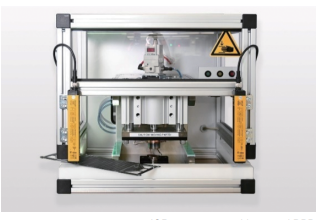
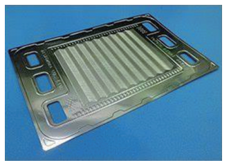
ICR test systems are presently not yet readily available in the market. As Ionbond already offers various customers coating service for BPP plates of both FCs and electrolyzers, Ionbond has to measure the ICR at different sizes of BPPs. In order to do so, Ionbond has developed an ICR test system with controlled contact pressure varying between 0.1 and 1.5 MPa, whereby small test samples as well as real size BPPs can be measured non-destructively. This is possible through slits in the side wall of the equipment. The picture shows a small BPP in the corner, pointing out the slits. As high contact pressures with a hydraulic system are involved, safety of the operator is provided by light curtain interlocks.
Ionbond has also installed a corrosion test cell. With the test cell, corrosion is simulated in a 24 or 48 h cycle. For the simulation, the H2SO4 medium described by DOE is usually used, but other (confidential) media can be used according to customers’ requests.
As both companies are focusing on different market segments, two different solutions have been developed and released for production.
Modified carbon coating system developed at Hauzer
Diamond like carbon (DLC) coatings have been present in the commercial market for approximately 25 years. For the FC application Hauzer has developed a modified carbon coating for stainless steel BPPs. The DLC coating is applied in 2 steps. Firstly, an adhesion layer of a thin metal layer is deposited by Physical Vapor Deposition (PVD). Secondly a thin carbon layer is deposited on top by PVD. The coating package which contributes to the improvement of conductivity and corrosion resistance has been cost-optimized. Where academic solutions typically show a thickness of over 1 μm, the Hauzer-developed coating package has a total coating thickness of less than 300 nm.
Different metal adhesion layers and different carbon layers have been tested to optimize the functional properties for minimal out-diffusion of metal ions from the BPP into the electrolyte, and for a low and stable ICR level during FC operation.
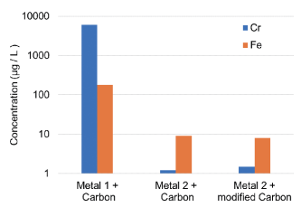
In the first test, the electrolyte composition is measured by ICP-MS (Inductively Coupled Plasma Mass Spectrometry) after very harsh test conditions to check for any contaminations from metal ions from the BPP. The test was carried out by Fraunhofer Institute for Solar Energy Systems using 20 min static polarization at 1.4 V, 80°C, O2 saturation. In general, the contamination level is greatly determined by the ability of the coating to block the out-diffusion of metal ions and is seen as a good prediction of the expected lifetime of a FC stack. The graph shows that the concentrations of Cr and Fe in the electrolyte are much lower in case Metal 2 is used as adhesion layer. The type of carbon does not seem to play an important role.
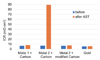
In the second test, a small FC stack is assembled and tested under accelerated conditions (so-called Accelerated Stress Test, or AST) by ZBT institute in Germany (The hydrogen and FC center). The coating performance is determined by measuring the ICR levels before and after the 500 h AST.
The test shows that these levels remain well below the DOE target of 10 mΩ∙cm2 after 500 h AST, except for the coating combination of Metal 2 layer and carbon coating.
In conclusion, the best results were obtained with Metal 2 and modified carbon. In the meantime, these coatings have been produced successfully at Ionbond for pre-production series of Hauzer customers.
For high volume production, Hauzer is bringing in its Flexliner® inline platform. Flexliner® systems are running in different industries for many years up to now. For BPP coating, the platform is configured for two-side coating, multiple processes in parallel at high speed to enable lower cost levels.
About 15 to 50 BPPs, depending on BPP size, are loaded on every carrier at a speed of one carrier per minute. Each carrier enters the PVD system on one side, travels through multiple process zones (etching, deposition of metal, and deposition of carbon), and leaves the system on the other side. The modules are designed to enable the implementation of processes developed in the standard batch-type F1500 units for etching and deposition, optimal operator accessibility, and less maintenance time.
Coating system based on droplets at Ionbond
Ionbond has worked on a coating system, where Au or Pt droplets are sprayed on Ti. For stainless steel BPPs, a Ti layer is deposited by PVD first. For Ti BPPs, the droplets are sprayed directly onto the BPP. For both cases Ti is oxidized afterwards to form TiO2. This process has originally been invented by Treadstone Technologies (http://www.treadstone-technologies.com) and is called “DOT technology.”
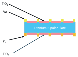
The final coating solution essentially splits the ultimate functionality. The droplets of Au or Pt take care of the electrical conductance, whereas the TiO2 provides the anti-corrosion and anti-diffusion barrier.
Besides the technologically interesting solution, this offers a way to come to much cheaper BPPs and stacks. The typical solution is based on full film Pt layers, where this DOTs process uses only a fraction of the precious metals (2 to 10% surface area coverage). Also, there is now a free choice on what precious metal to apply on either cathode or anode side of the BPPs.
The spraying of Au or Pt droplets is a thermal spray process, in which firstly an emulsion is made which contains the Au or Pt powder. The emulsion is pumped by means of a very accurate small volume pump into the flame of a high-power burner. The powder is melting in the flame and arrives at the BPP surface as droplets/splashes. The droplets are considerably smaller than the original powder size. To avoid overheating and possible local melting of the often very thin BPP, the BPP is transported forward and backward through the flame by a fast and controlled linear movement.
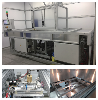
Furthermore, the burner platform is slowly moved sideways, so that a complete surface of the BPPs gets coated. At Ionbond a small-scale production unit has been constructed, which is presently running for pre-production series and has a capacity of 20 000 m2/y.
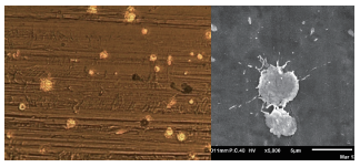
The shape of the splashes of Au or Pt depends on the process conditions. Ionbond has run an extensive test program to define a safe operating window. A typical example of a surface of stainless steel, first PVD coated with a thin Ti layer and then coated with Au DOTs, is shown.
The effective surface coverage of the DOTs can be steered by the process conditions of the flame spray process. The effective surface coverage is driving the ICR values of the BPP. A higher coverage results in lower ICR values.
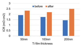
The corrosion protection is set by the TiO2 layer as formed by a thermal heat treatment process after the spraying of the droplets. To test the influence of the thickness of the Ti layer on corrosion and ICR of stainless steel BPPs, three different thicknesses of PVD Ti were tested: 50 nm, 100 nm, 200 nm. Ti was oxidized after the Au DOTs were deposited. ZBT measured ICR values before and after 24 h static polarization. The results are shown in the upper figure on the right. There is only a small shift in the ICR, but there is not a significant influence of the Ti thickness on ICR before and after polarization.
The risk for hydrogen embrittlement is also considerably reduced by the TiO2 barrier coating.
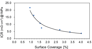
For Ti BPPs, frequently used in electrolyzers, Pt DOTs have been sprayed and the ICR has been measured for various surface coverage percentages.
The lower figure on the right shows that ICR below 10 mΩ∙cm2 is reached already at a surface coverage of 2%.
Future outlook
It has been demonstrated that stainless steel BPPs can be coated in mass volume economically and with high quality using a stack of a base layer of metal and a thin coating of carbon on top for both passenger as well as commercial vehicle applications. Hauzer has designed coating equipment for mass volume production with yearly volumes of over 10 million parts.
For applications where expected lifetimes are higher an alternative has been designed based on highly conductive paths of Au and/or Pt droplets, with a layer of TiO2 in between the highly conductive droplets. TiO2 prevents further corrosion and also reduces hydrogen embrittlement of Ti BPPs. Further enhancements can be expected by further optimization of the precious metal usage through optimization of the spray conditions, splash shapes, and BPP surface preparations. A new vertically based machine concept is in the engineering stage for further throughput increase as well as more ergonomic running and maintenance by Ionbond employees.
By improving the performance and the productivity of FC’s and electrolyzers, through coating technologies, IHI contributes to global decarbonization.