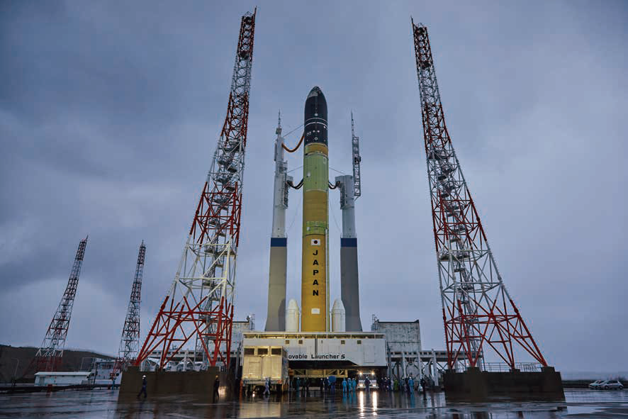
Ever-Evolving Solid Rocket Booster SRB-3, a solid rocket booster contributing to “high cost-performance, high flexibility, and high reliability” in H3/Epsilon S launch vehicles
IHI AEROSPACE Co., Ltd.
H3 and Epsilon S launch vehicles are being developed to increase the presence of Japan’s space transportation industry in the commercial satellite market. IHI AEROSPACE Co., Ltd. developed SRB-3, a solid rocket booster for the H3, with a view of using it as a first-stage motor for Epsilon S launch vehicles. This article introduces the technological development conducted so far and future prospects.
Taking the lead in space transportation with H3 launch vehicles
The H3 is being developed as a successor to the H-IIA/B, Japan’s current mainstay launch vehicles. The aim with the H3 is to take the lead in the commercial satellite market and space transportation industry in the 2020s and later by significantly reducing launch costs and improving usability while inheriting the high reliability from the H-IIA/B. The development concept of the H3 is “high cost-performance, high flexibility, and high reliability.”
IHI AEROSPACE Co., Ltd. (IA) developed the solid rocket booster for the H3 (SRB-3), which is a successor to the solid rocket booster for the H-IIA (SRB-A) under the Japan Aerospace Exploration Agency (JAXA). We developed the SRB-3 with the following goals based on the H3’s development concept.
- 【High cost-performance】
- Minimizing functional parts mounted on the SRB-3 is supposed to make the SRB-3 attractive in price to the commercial satellite market. Reviewing its materials and manufacturing processes is also another way to reduce costs.
- 【High flexibility】
- Shortening the interval between launches from the current two months to one month is required to increase launch opportunities. To achieve this flexibility in schedule, we planned to simplify the work of connection with the core airframe and reduce inspection-related work in the operation of the SRB-3.
- 【High reliability】
- To inherit the high reliability of the current models, we worked on sophisticating analysis with use of the designing and manufacturing know-how we had accumulated.
To achieve these goals, development was carried out as follows.
- (1) Innovation of a connection/separation system
- -Shortening the maintenance period by reducing connecting points between the core airframe and SRB-3 to a minimum
-Reducing functional parts by integrating their functions for separation - (2) Developing a made-in-Japan motor case
- -Made-in-Japan motor case development for enhanced flexibility in meeting operational requirements
-Improving the flexibility of material procurement through development with domestic materials - (3) Reducing the solid rocket motor’s costs with inherited high reliability
- -Utilizing the know-how of SRB-A’s nozzle design
-Development for cost reduction through material development and enhancement of manufacturability -Sophisticating the method of combustion performance analysis - (4) Halving the period for launch site maintenance
- -Enhancing operability by integrating the handling function into the booster
-Embedding the inspection function into the safe arm device (SAD)
Innovation of a connection/separation system
In the separation system of the SRB-A for the H-IIA, the booster is separated from the core airframe through the mechanism of a structure with long poles called thrust struts, which are located on both sides of the booster, just as in the case of pole-vaulting. This method is advantageous in terms of structural strength because the main thrust load is transferred dividedly to both sides of the booster. However, this system requires as many as eight separation devices due to the presence of numerous connecting points, which causes an increase in costs.
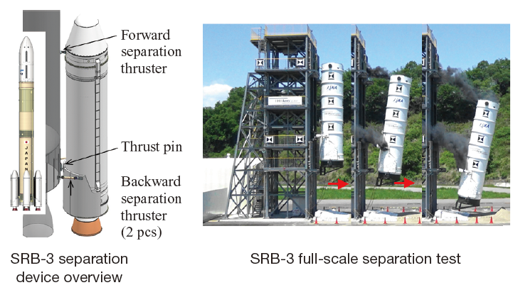
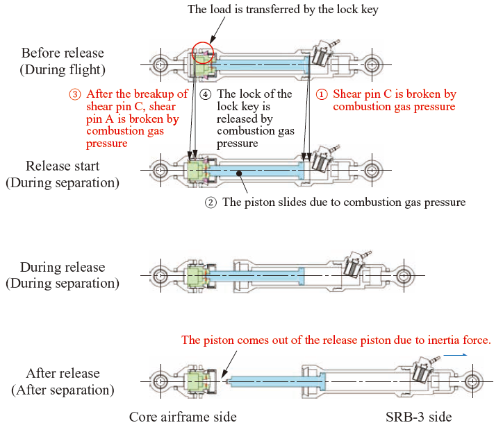
In the SRB-3, therefore, we changed the separation method. In this method, the thrust of a gas actuator called a separation thruster accelerates the booster whose connection with the core airframe has been released, preventing the booster from colliding with the core airframe. Thanks to this change of the method, we achieved to reduce the number of connecting points, resulting in shortening of the maintenance period required to connect the core airframe and SRB-3 on the launch pad. In addition, as described in the release process overview, it allows the system to integrate the functions of connection release and separation, and drastically cuts the number of separation devices from eight to three.
As this method has not been employed in boosters with 65 t of propellant before, this introduction is the world’s largest case. The separation thruster for this method requires a large amount of energy to accelerate the airframe of 9.3 t to approximately 4 m/s in 0.2 s. On the other hand, the system needs to minimize the load of the reaction force received by the core airframe, and cannot employ the method of adiabatically expanding combustion gas generated instantly because it produces an excessive load. Thus, we developed a gas generator that can control the load by using propellant to adjust the amount of generated combustion gas. We then selected a propellant whose combustion gas temperature is low to mitigate the heat load on the separation thruster’s mechanical section. To make it smaller to streamline the outfitting work, the propellant has a dendritic configuration that can maximize the burning area. The system also requires a function to slide a piston in the separation thruster properly when it receives a lateral force of approximately 30 kN during flight. For this requirement, we developed a low-friction bearing and a sealing part including its material and shape by applying the pyrotechnics technology in which we excel. The separation thruster completed with these technologies was used to verify the separation system in the entire SRB-3 unit in a full-scale separation test, ensuring its quality.
Developing a made-in-Japan motor case
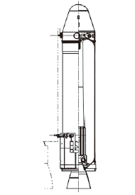
A motor case has strength against the propellant’s combustion pressure and thrust load applied in the direction of the airframe axis. IA has technology to co-cure a lightweight motor case of carbon fiber-reinforced plastic (CFRP) with a filament winding (FW) method.
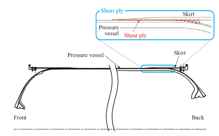
SRB-A had restrictions on load conditions because it was developed with technology introduced from abroad and included an existing motor case. With the SRB-3, however, we developed a new motor case to be produced in Japan, resulting in elimination of the restrictions on load conditions and significant enhancement in operability. To apply the separation system outlined in the previous section, we needed to drastically increase the joint strength between a skirt that transfers load at the motor case’s back end and a shear ply, which is rubber for transferring the load to the pressure vessel (both of them are shown in the motor case overview). This was a technological challenge. The shear ply transfers thrust load that is applied in the direction of the airframe axis while absorbing strain from the pressure vessel generated by the internal pressure load, which is the core part of the motor case design. To increase the joint strength, we developed our original domestic material for shear-ply rubber and established the design and manufacturing technology for the joint part, so that it has 2.4 times the joint strength of SRB-A’s. In addition to the shear ply, we also replaced all the materials, including CFRP, for the pressure vessel with domestic ones to make material procurement more flexible and reduce costs.
Reducing the solid rocket motor’s costs with high reliability inherited
The SRB-A has high specific thrust due to its high combustion pressure (11.8 MPa). Conversely, the high-pressure combustion produces a high heat load, which resulted in an accident caused by local erosion on the nozzle in the H-IIA6. IA strived to improve the internal shape of the nozzle to solve the problem, and obtained design and manufacturing technology for a highly reliable high-pressure combustion motor. To make the SRB-3 highly reliable, we focused on not producing local erosion on the nozzle with use of the technology established in the SRB-A’s development.
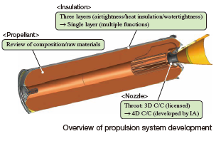
In developing the propulsion system, we worked to reduce costs without sacrificing high reliability with the aim of enhancing market competitiveness of the H3 by employing new materials for the system and simplifying manufacturing processes, albeit with some restrictions such as the nozzle shape.
- (1) Review of propellant’s composition and raw materials
- The manufacturing process was improved so that some of the raw materials that used to require equipment exclusively for them could be manufactured with general-purpose equipment.
- (2) Single-layering of insulation
- The internal surface of the SRB-A’s motor case is equipped with insulation rubber consisting of three layers with respective functions to maintain airtightness and heat insulation during propellant combustion and watertightness for pressure testing conducted in manufacturing. A single-layered insulation material that integrates and satisfies these functions has been developed to reduce costs through shortening the production period.
- (3) Change of nozzle throat material
- The throat with the shortest diameter in the entire nozzle is exposed to high-temperature combustion gas and high combustion pressure. To resist such a harsh environment, the throat is made of a carbon-carbon composite (C/C). The preform for curing this C/C used to be a three-dimensional carbon-carbon composite (3D C/C) manufactured under license, but that in the SRB-3 was altered to a four-dimensional carbon-carbon composite (4D C/C) developed by IA to reduce costs through automation and shorten the production period.
In addition to these cost-reduction methods, we sophisticated the method of analyzing combustion performance. This made it possible to calculate combustion performance with the optional three-dimensional grain shape, which used to be difficult to handle, and enhanced design freedom and prediction accuracy for system requirements.
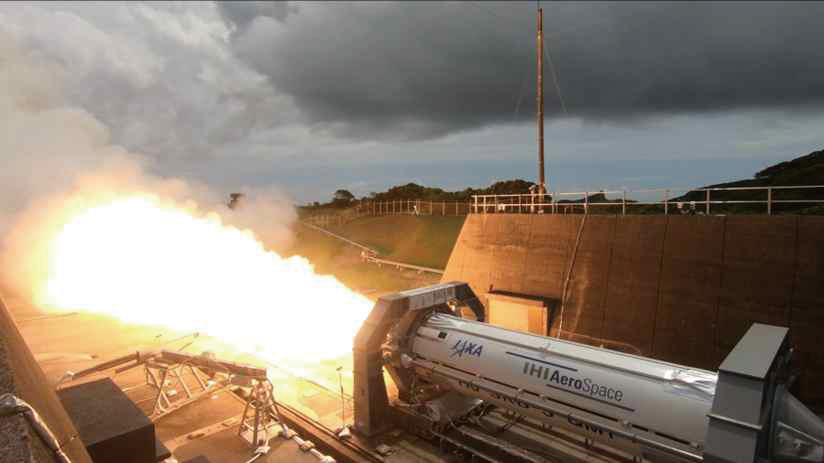
Based on the above development, the performance was checked in three ground-firing tests.
Halving the period for launch site maintenance
For the H3, we set the goal of halving the period for maintenance at a launch site to shorten the interval between launches, which was the bottleneck in scheduling, and to increase launch opportunities. In launch site maintenance, connecting the booster to the core airframe is the main task, and is carried out through the following processes (1) to (4) in the H-IIA. In (1) and (4), it was necessary to attach/detach a large handling jig whose outer diameter is the same as that of the booster. That took a significant amount of time.
(1) Installing a hoisting accessory on the solid rocket booster (SRB-A)
(2) Erecting the SRB-A with a crane
(3) Connecting and outfitting the core airframe and the SRB-A
(4) Removing the SRB-A’s hoisting accessory and attaching a nose cone
Therefore, the SRB-3 was designed to integrate the function of the handling jig into the booster’s front structure to eliminate the work of attaching/detaching the large jig, and to be connected to the core airframe in a completed state with a nose cone attached to it. In February 2021, handling a booster with such a front structure was proved to be possible in the work of connecting it with a core airframe that was conducted as a part of an integrated system test (IST) of the H3 launch vehicle. While it was possible to connect one booster with a core airframe in a day in the case of the SRB-A, the number of such boosters is increased to two in the case of the SRB-3, making it possible to halve the period for launch site maintenance.
Aside from the connection work, there are other items that contributed to reducing maintenance period. For example, the smart SAD, which was developed simultaneously with the SRB-3, made it possible to eliminate the task of attaching/detaching cables exclusively for inspection during launch site maintenance by embedding the inspection function into the SAD.
Future prospects
The SRB-3, which was developed by IA this time, is planned to be adopted in the first-stage motor for the Epsilon S, for which IA is carrying out development to participate in the launch service, as well as the H3 launch vehicles. The goal is to launch the first Epsilon S launch vehicle equipped with the SRB-3 in fiscal 2023.
At the moment, positioning, communication, and broadcast satellites are important infrastructure for supporting the digital society; they are becoming smaller and increasingly work in a constellation. The demand for launch services is rapidly increasing amid the expansion of the commercial satellite market. We will keep working on development of the SRB-3, which is to be employed both in the H3 and Epsilon S, to make it a pillar of our space transportation business under these circumstances.
We will keep contributing to increasing Japan’s presence in the space transportation industry with our superior manufacturing capabilities developed based on our manufacturing and operation experience, and through further technological advancement.