Development of Liquid Ammonia Direct Spray Combustion Gas Turbine
UCHIDA Masahiro, ITO Shintaro, SUDA Toshiyuki
UCHIDA Masahiro : Doctor of Engineering, Manager, Energy Conversion Group, Technology Platform Center, Technology & Intelligence Integration
ITO Shintaro : Doctor of Engineering, Manager, Energy Conversion Group, Technology Platform Center, Technology & Intelligence Integration
SUDA Toshiyuki : Doctor of Engineering, Manager, Strategic Project Department, Corporate Strategy Headquarters
Liquid ammonia direct spray combustion technology was developed to use ammonia as fuel for gas turbines. As a result of the verification test, it was demonstrated that it is possible to burn liquid ammonia up to a co-firing ratio of 70% while suppressing the concentration of harmful substances in the exhaust gas. It was also confirmed that the emissions of unburned ammonia (NH3) and nitrous oxide (N2O) were below the regulation values in Japan, thus the environmental impact of operating the ammonia-fueled gas turbine was minor.
1. Introduction
To conserve the global environment, decarbonization efforts are underway in various fields. In the electrical power industry, renewable energy, as represented by solar energy and wind energy, has been rapidly adopted, but thermal power generation remains important for power grid stabilization by balancing supply and demand. In particular, gas turbines are superior in terms of responsiveness to load changes and are expected to continue to be used. Therefore, shifting gas turbine fuels to carbon-neutral ones will contribute to both reducing carbon dioxide (CO2) emissions and stabilizing the power grid.
Hydrogen is a typical carbon-neutral fuel. However, although hydrogen is easy to burn as a fuel, it is difficult to transport and store hydrogen because of its thermophysical properties. Therefore, the Cabinet Office of Japan carried out SIP (Cross-ministerial Strategic Innovation Promotion Program) Energy Carrier(1) project. In the project, liquid hydrogen, methylcyclohexane, and ammonia are focused on as energy carriers for transporting hydrogen. The project compared and studied their usability and issues as well as conducted relevant technology development. Among these energy carriers, ammonia is advantageous because it can be liquefied easily and is suitable for transport and storage. In addition, the technologies for transporting and storing ammonia have already been established. Another advantage of ammonia, which is flammable, is that it can be burned directly without dehydrogenation as an alternative to hydrocarbon fuel. However, ammonia has low flammability and must be handled with care as it is a deleterious substance. In addition, when burned, ammonia is likely to generate Fuel-NOx, which is derived from the nitrogen atoms contained in fuel. To overcome these challenges and to promote the use of ammonia as a fuel by making the most of its characteristics, efforts have been made to clarify the basic combustion characteristics and to develop combustion technologies(2).
There are two primary potential methods to supply ammonia when burned in power generation gas turbines: the ammonia gas method and the liquid ammonia direct spray method. At ambient temperature, ammonia undergoes a phase change at approximately 0.8 MPa; therefore, ammonia is generally gasified before burning so long as the combustor pressure is around atmospheric pressure. However, gas turbines are pressurized, and the combustor pressure is high. In general, medium and large gas turbines have a combustor pressure of 0.8 MPa or more; therefore, ammonia can be sprayed stably in a liquid state. Taking advantage of this characteristic, we developed a technology to burn ammonia by directly spraying it into a combustor in a liquid state based on conventional technology to co-fire ammonia gas with natural gas(3). This article reports on the features of combustion methods using liquid ammonia and ammonia gas as well as the results of a verification test using gas turbines.
2. Test system
Figure 1 is a schematic showing the system flow of the ammonia-fired gas turbine verification test facility. This facility consists of a city gas compressor, ammonia supply equipment, 2-MW-class gas turbine, and denitration equipment. The ammonia supply equipment supplies ammonia gas for denitration, fuel ammonia gas, and liquid ammonia from the ammonia tank. With regard to the fuel supply system, the systems for ammonia gas and liquid ammonia are given for comparison.
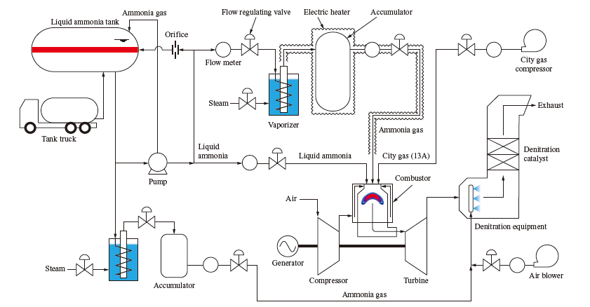
The fuel ammonia gas supply system consists of a pump for pressurizing liquid ammonia, a vaporizer, and an accumulator. For ammonia gas supply, liquid ammonia is pressurized by the pump, supplied to the vaporizer after the flow rate is adjusted, and vaporized by hot water heat. The vaporized ammonia is passed through the accumulator to stabilize the pressure, then supplied to the gas turbine. A feature of this supply method is that because ammonia is pressurized in a liquid state, the power required for pressurization is less than when ammonia is pressurized in a gas state; in addition, ammonia can be vaporized by a heat source with a relatively low temperature. Another advantage of this method is that because the combustion behavior is not affected by the latent heat of vaporization, it is relatively easy to clarify the basic combustion characteristics and to develop combustion technologies for use with gas turbines. However, vaporizing ammonia requires a heat source, albeit one with a relatively low temperature. In addition, ammonia gas in the vaporizer downstream may be turned back into liquid ammonia due to loss of heat into the surroundings; therefore, it is necessary to keep the piping and accumulator hot using electric heaters.
To burn ammonia gas in a gas turbine, adequate supply capacity must be ensured by using a larger vaporizer and accumulator or by arranging multiple vaporizers and accumulators in parallel. Meanwhile, with the liquid ammonia direct spray method, pressurized liquid ammonia is sprayed directly into the combustor while controlling the flow rate. This method does not require an ammonia vaporizer or an accumulator, which are required by the ammonia gas method, and can thereby supply ammonia into the gas turbine with a simpler supply system. Also, another advantage is that, because the ammonia supply capacity depends only on the pump capacity, the cost of increasing ammonia supply can be reduced. A further advantage of this method is that there is no need to warm the ammonia vaporizer, making it possible to significantly reduce the time needed to start ammonia supply. In addition, with the ammonia gas supply method, a gas turbine’s capability to respond to rapid load changes depends on the accumulator capacity, but with the liquid ammonia direct spray method,the capability can be adjusted easily with a pump or flow regulating valve, which is another advantage. Because of these features, the liquid ammonia direct spray method is suitable for use with small and medium gas turbines, which are used for DSS (Daily Startup and Shutdown) operation and load balancing. Regarding combustion behavior, however, with this method, liquid ammonia evaporates in the combustor; therefore, misfire due to a locally low flame temperature is a concern. In addition, a challenge to overcome is that the temperature of the combustion gas flowing into the gas turbine decreases due to the latent heat of vaporization, which reduces the efficiency of the gas turbine.
A 2-MW-class IM270 gas turbine, manufactured by IHI,was used for the verification test. For this gas turbine, only the combustor was newly developed; as for the compressor and turbine, existing commercial models were used. In combustor development, the combustor design is required to achieve both stable combustion and reduced nitrogen oxide (NOx) emissions. It is known that the rich-lean two-stage combustion method is effective to achieve these conditions(2), (4), so this combustion method was applied to the combustor for the 2-MW-class gas turbine. Figure 2 is a schematic of the developed combustor. A turn flow-type single-can combustor was adopted for this gas turbine, and the combustion air is compressed by the compressor and supplied through the flow channels on the outer side of the liner. The amounts of combustion air supplied to the burner and dilution hole on the liner are adjusted in order to adjust the mixing ratios of fuel and air in the primary and secondary zones of the combustor, thereby realizing two-stage combustion. All fuel is supplied to the primary zone.
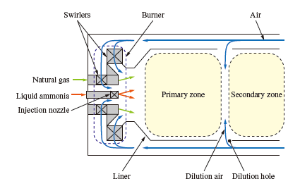
When ammonia is used as a liquid fuel, the rate of latent heat of vaporization to the calorific value per unit weight becomes larger compared with hydrocarbon liquid fuel (e.g., kerosene), and the flame temperature decreases more significantly by the latent heat of vaporization. To achieve stable combustion and to reduce unburned ammonia emissions, we adopted a burner swirler that enables a strong swirl flow for adjusting the fuel injection position. To reduce the NOx emissions, the distribution of air to the primary zone was optimized for liquid ammonia direct spray combustion.
During the verification test, we conducted performance measurement at different mixing ratios of natural gas and ammonia with the power output fixed at 2 MW. In the gas turbine test, we sampled combustion gas at the outlets of the turbine and denitration equipment to evaluate emission. In the performance evaluation for ammonia combustion, in addition to the flue gas components measured with standard flue gas analyzers, unburned ammonia and nitrous oxide (N2O) may be emitted. Under Japanese emission regulations, N2O is included in NOx, but it has a global warming potential approximately 300 times higher than CO2; therefore, concentration measurement is essential to accurately measure the GHG (GreenHouse Gas) emissions reduction effect of the ammonia combustion gas turbine. In flue gas component evaluation, we used both a NDIR (Non-Dispersive InfraRed spectroscopy) analyzer and a QCL-IR (Quantum Cascade-Laser InfraRed spectroscopy) analyzer to measure the concentrations. The NDIR analyzer was used to measure the concentrations of oxygen (O2), carbon monoxide (CO), carbon dioxide (CO2), and total hydro carbon (THC), while the QCL-IR analyzer was used to measure the concentrations of nitrogen monoxide (NO), nitrogen dioxide (NO2), nitrous oxide (N2O), and ammonia (NH3).
3. Test results
As a result of the power generation verification test using the 2-MW-class gas turbine, it was found that when liquid ammonia is burned with a mixing ratio of 70% or less, the concentrations of hazardous substances in the flue gas can be kept low. Here, the ammonia mixing ratio was defined as the percentage of the input heat quantity of ammonia to the total input quantity of the fuels (ammonia + natural gas) that were calculated based on the lower calorific value.
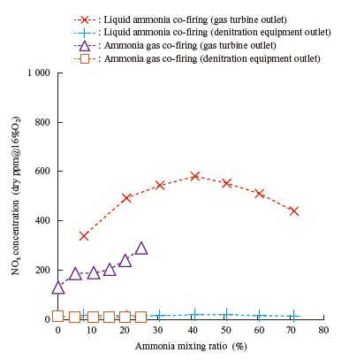
Figure 3 shows the effect of the ammonia mixing ratio on the NOx concentration. This represents the relationship between the ammonia mixing ratio and the concentrations of NOx in the flue gas sampled at the gas turbine’s outlet and at the denitration equipment’s outlet which were obtained during the gas turbine test. The NOx concentration indicates the sum of the NO, NO2, and N2O concentrations. The measurement result obtained by co-firing ammonia gas(3) is given for comparison. As the ammonia mixing ratio increases, the NOx concentration increases monotonically. It peaks when the mixing ratio reaches 40% and then decreases. This tendency of the NOx concentration is caused by the effect of the temperature in the ammonia combustion section. As the ammonia mixing ratio increases, the amount of ammonia supplied into the combustor increases monotonically. As the amount of ammonia supplied increases, the flame temperature in the ammonia combustion section decreases because the flame temperature of ammonia is lower than that of natural gas. When the temperature decreases, the quantity of nitrogen atoms in ammonia that turn into nitrogen (N2) and NOx changes, and under these conditions, the NOx concentration peaks. Although the mixing ratio is limited to 25%, when liquid ammonia combustion and ammonia gas combustion are compared, overall, the NOx concentration tends to be higher when liquid ammonia is burned. This is presumably because air-fuel mixing conditions differ between liquid ammonia and ammonia gas. With regard to the NOx concentration at the denitration equipment’s outlet, it was confirmed that NOx can be treated sufficiently with the denitration equipment included in the verification test system and that the NOx concentration conforms to Japan’s environmental standard (70 ppm).
Regarding the measurement results of unburned ammonia concentration, because unburned ammonia emissions are suppressed when the gas turbine is under high-pressure combustion conditions, the unburned ammonia concentration is extremely low (5 ppm or less) under all conditions, and the impact of ammonia combustion with the gas turbine on the surroundings is minor.
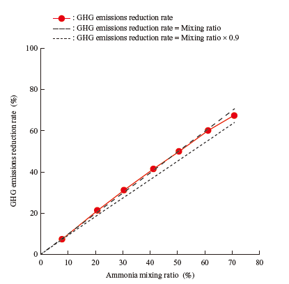
With regard to the N2O concentration, which is important for quantitatively evaluating the GHG emissions reduction effect, a small amount of N2O was confirmed with the liquid ammonia direct spray combustion method. This is because liquid ammonia evaporates in the combustor and the flame temperature decreases, causing the flame temperature to be low in some areas where N2O is readily generated. Figure 4 shows the effect of the ammonia mixing ratio on the GHG emissions reduction rate. When the liquid ammonia mixing ratio is 70%, the consumption of natural gas is reduced by 70%, which means that under ideal conditions, a GHG emissions reduction effect of 70% can be obtained. We calculated the actual GHG emissions reduction rate in consideration of N2O and unburned ammonia emissions, and found that it is 68% or more when the mixing ratio is 70%. It was thus confirmed that a high GHG emissions reduction effect can be obtained at the current emissions concentration level.
4. Conclusion
Aiming to contribute to reducing the GHG emissions by increasing the amount of ammonia as a fuel in gas turbines, we have developed a combustion technology for spraying liquid ammonia directly into combustors. Compared to ammonia gas, liquid ammonia offers the advantages of being able to use a simpler supply system and better controllability. As a result of a verification test using a gas turbine, it was found that when liquid ammonia is burned with a mixing ratio of 70% or less, the concentrations of hazardous substances in the flue gas can be kept low. As for emissions, slight amounts of unburned ammonia and N2O were confirmed under high mixing ratio conditions, but their concentrations are extremely low and their impact on the environment and gas turbine operation is minor. It was also confirmed that the GHG emissions reduction effect is little affected by N2O emissions. Meanwhile, social demand to reduce GHG emissions continues to increase, and an ammonia combustion gas turbine that emits almost no GHG will be required in the future. To achieve this, there is a need for a combustor that can stably burn liquid ammonia while suppressing emissions. We will continue development to realize a liquid ammonia combustion gas turbine.
— Acknowledgments —
This paper is based on results obtained from a project (JPNP16002) commissioned by the New Energy and Industrial Technology Development Organization (NEDO). We would like to express our gratitude here.
REFERENCES
- Japan Science and Technology Agency: Energy Carrier, Cross-ministerial Strategic Innovation Promotion Program (SIP) : < https://www.jst.go.jp/sip/pdf/SIP_energycarriers2016_en.pdf >, accessed 2021-11-16
- H. Kobayashi, A. Hayakawa, K. D. K. A. Somarathne and E. C. Okafor : Science and Technology of Ammonia Combustion Proceedings of the Combustion Institute, Vol. 37, No. 1, 2019, pp. 109-133
- S. Ito, M. Uchida, T. Suda and T. Fujimori :Demonstration Test of Ammonia/Natural Gas Co-Firing Power Generation with 2 MW Class Gas Turbine, Journal of the Combustion Society of Japan, Vol. 61,No. 198, 2019, pp. 289-292
- S. Ito, M. Uchida, T. Fujimori and H. Kobayashi :NOx Emission of Two-stage Combustor for Ammonia/Natural Gas Co-Fired Gas Turbine, 12th Asia-Pacific Conference on Combustion, July 2019, Paper No. 1 279