Effects and Countermeasures on Deposit Ash of Biomass Single Fired Power Plant
SATO Naoki, OKUHARA Hirohito, WADA Chikako, MATSUNAGA Yasuo, OHNO Emi
SATO Naoki : Doctor of Engineering, Formerly of Applied Physics & Chemistry Group, Technology Platform Center, Technology & Intelligence Integration
OKUHARA Hirohito : Applied Physics & Chemistry Group, Technology Platform Center, Technology & Intelligence Integration
WADA Chikako : Applied Physics & Chemistry Group, Technology Platform Center, Technology & Intelligence Integration
MATSUNAGA Yasuo : Manager, Manufacturing Process Group, Technology Platform Center, Technology & Intelligence Integration
OHNO Emi : General Manager, R&D Department, Engineering Center, Carbon Solution Business Unit, Resources, Energy & Environment Business Area
Biomass fuel is practically co-fired as a carbon-neutral fuel with coal in coal-fired thermal power plants to reduce CO2 emissions. In Japan, various actions toward biomass single firing are currently promoted for the achievement of the 2050 carbon neutrality target. As for a biomass fired boiler, however, the ash deposition on boiler tubes may accelerate the reduction of thermal efficiency and the corrosion of the tubes because the biomass ash has chlorine and high alkali content despite its low ash. In order to develop countermeasures against ash deposition and corrosion, we conducted an ash deposition test with a horizontal furnace and a drop tube furnace and a corrosion test with an electric furnace and obtained a better understanding about their characteristics.
1. Introduction
As a measure against global warming, Japan has set a goal of achieving net-zero greenhouse gas emissions by 2050. In addition, efforts are underway to reduce dependence on inefficient coal-fired power generation in a phased manner, and even for high-efficiency coal-fired power generation, reducing CO2 emissions remains a major issue. Given such circumstances, there is increasing adoption of carbon-neutral biomass fuel, which enables effective use of existing facilities, can be used as an alternative fuel for coal-fired power generation.
The IHI Group has been delivering boilers with a biomass mixing ratio of 25% or more and receiving orders to convert power generation boilers into wood biomass single fired boilers(1).
Making effective use of biomass, which is a carbon-neutral fuel, helps to achieve net-zero carbon emissions and also makes it possible to become carbon negative by capturing, utilizing, and storing CO2 from flue gas. Recently, an increasing amount of biomass fuel, ranging from wood pellets to agricultural residue pellets, has been put into practical use.
Previously, we introduced our efforts to increase the biomass mixing ratio in biomass boilers(2), (3). This paper will introduce challenges for biomass single firing by focusing on the effects of deposited ash on boiler tubes and countermeasures for deposited ash.
2. Challenges for biomass single firing
Regarding the wood biomass used in pulverized coal-fired boilers for coal-fired power generation, in general, wood pellets are mainly used because of their stable shape and properties. However, if an existing pulverized coal-fired boiler is modified for biomass single firing, one problem is that the facilities are designed in consideration of the properties of coal, not those of biomass fuel.
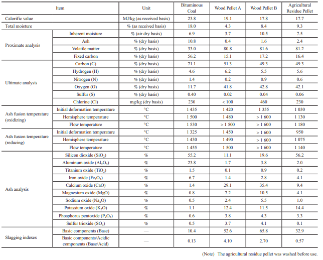
Table 1 lists fuel properties. This table compares the properties of bituminous coal with those of wood pellets, both of which are commonly used in Japan, and those of agricultural residue pellets. In the future, it is expected that in addition to wood pellets, herbaceous biomass and agricultural residue pellets will be used; therefore, in this study, wood pellets and agricultural residue pellets are compared to bituminous coal.
2.1 Fuel properties
The following summarizes the characteristics of biomass fuel based on the properties listed in Table 1.
- (1) Calorific value
- In general, biomass pellets have a calorific value that is 20 to 30% lower than bituminous coal. Therefore, consideration must be given to the capacity of storage and other facilities.
- (2) Proximate analysis
- The volatile matter is as high as around 80%, and the ash is only a few percent or less, which means that the flammability of biomass fuel is quite different from that of coal. Because of this difference in flammability, the air supply balance needs to be adjusted. Also, because biomass fuel generates less ash, the tendency is for a relatively smaller amount of ash to be deposited on boiler tubes and for a relatively smaller amount of ash to be recovered.
- (3) Ultimate analysis
- The oxygen (O) content is higher, which facilitates combustion. The nitrogen (N) content and sulfur (S) content are lower, which means that the amount of nitrogen oxides (Fuel-NOx) generated by the oxidation of N can be reduced, and sulfur oxides (SOx) can also be reduced significantly.
- (4) Ash fusion temperature and ash analysis
- Biomass pellets tend to have a lower ash fusion temperature than coal, but the value differs significantly depending on the biomass type. Regarding ash composition, in general, while coal contains much silicon dioxide (SiO2) and aluminum oxide (Al2O3), biomass pellets contain far more sodium oxide (Na2O), potassium oxide (K2O), and calcium oxide (CaO) than coal.
2.2 Slagging properties
Figure 1 shows the troubles caused by ash in boilers. It is known that in boilers, slagging and fouling occur depending on ash properties, and these affect boiler operation(4)–(6). Once ash has been deposited on a boiler tube and grows, it cannot be removed easily. The deposited ash sometimes inhibits heat transfer and changes the thermal balance within the boiler significantly, making it impossible to achieve the required performance. If ash deposits grow, the flue gas pressure loss in the boiler increases, necessitating that the operational load be decreased. Therefore, to ensure stable boiler operation, it is important to prevent ash from depositing and growing as well as to ensure that ash can be removed easily even if it is deposited. In particular, evaluating the slagging properties on furnace walls and elsewhere is important, and we have been accumulating knowledge on this topic by operating coal-fired boilers over many years.
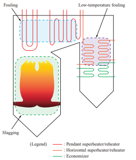
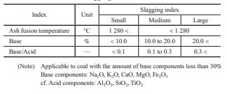
Table 2 lists the slagging indexes for coal. The empirical indexes such as slagging indexes and/or sintering factors based on the degree of sticking have been used for the stable operation of coal-fired boilers(7).
If these slagging prediction indexes for coal are applied to the biomass properties listed in Table 1, the total base content far exceeds 30%, and the base/acid content also differs greatly from that for coal, which means that the slagging properties for biomass cannot be evaluated with the indexes for coal and cannot be predicted easily. In addition, though the Cl concentration in biomass is almost the same as that in coal, it is concerned that biomass may enrich Cl content in generated ash because of forming a lot of chlorides due to its high alkali content. That is the effects of ash deposition and corrosion for biomass single firing is still unknown. Therefore, we decided to evaluate the slagging and fouling properties and the corrosion characteristics of biomass fuel ash by using test equipment to determine new relationships between fuel properties and ash deposition and corrosion.
3. Ash deposition mechanism in biomass single firing
3.1 Purpose
As described above, biomass fuel contains more potassium (K) and calcium (Ca) than coal(8), and it causes ash deposition with a low ash fusion temperature, which, in biomass single firing, may make it difficult to remove ash deposits from heat exchange tubes. In addition, it is known that K and Ca react with Cl, which contributes to chloride deposition behavior, and chloride deposited on boiler tubes may accelerate corrosion(8), (9). Therefore, we conducted ash deposition tests simulating the boiler furnace temperature and boiler tube metal temperature to clarify the ash deposition and shedding behavior as well as the chloride deposition behavior.
3.2 Test facilities
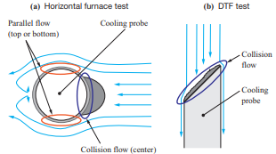
The tests were conducted using a horizontal furnace and a drop tube furnace (DTF) to evaluate the ash deposition behavior with different boiler flow fields. Table 3 lists the features of the test facilities used in the ash deposition test, while Fig. 2 shows the differences in the flow field between these test facilities. The horizontal furnace has a horizontal flow field with a higher fuel feed rate, and it was used mainly to conduct ash deposition tests under conditions simulating the inside of a furnace. Meanwhile, the DTF has a downward flow field with a lower fuel feed rate, and it was used mainly to conduct ash deposition tests under conditions simulating a rear heat transfer section. The fuels listed in Table 1 were used for these tests.
Table 3 Features of test facilities for ash deposition test
3.2.1 Horizontal furnace
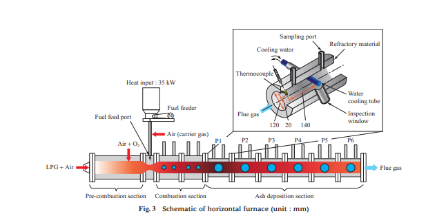
Figure 3 is a schematic of the horizontal furnace. The horizontal furnace is approximately 3 000 mm long and has an inner diameter of 120 mm. It consists of a pre-combustion section, combustion section (with a total length of approximately 800 mm), and ash deposition section. Its inner wall is coated with refractory material to minimize heat radiation. In the pre-combustion section, liquefied petroleum gas (LPG) is burned, and air and oxygen are injected to generate combustion air with a temperature of 1 000°C and an oxygen concentration of 21 vol%. Then, the fuel feeder feeds fuel from the fuel feed port to burn the fuel in the combustion section. As shown in Fig. 3, the ash deposition section consists of six blocks, P1 to P6, where the furnace temperature ranges from 800 to 1 400°C. In each test, to allow ash to deposit, a water cooling tube is inserted into the block for the temperature range to be measured.
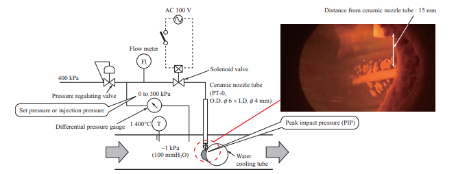
To quantitatively evaluate the ability to remove ash of the soot blower, which is boiler ash removal equipment, an air blower was used for measuring the peak impact pressure (PIP) at the time of ash shedding by air blowing. Figure 4 is a schematic of the air blower. The air blower consists of a pressure regulating valve, differential pressure gauge, flow meter, solenoid valve, and ceramic nozzle tube. The ceramic nozzle tube is inserted from the sampling port of the horizontal furnace (Fig. 3), and the pressure regulating valve is used to adjust the pressure of the air to be injected with differential pressure from inside the furnace. When the solenoid valve is opened, dry air is injected from the ceramic nozzle tube, which is installed vertically above the water cooling tube. The flow rate of the injected air was measured with the flow meter, the flow rate and injection pressure were recorded by a logger, and the pressure conditions at the time of ash shedding were measured. The PIP decreases as the distance from the ceramic nozzle tube outlet increases, so it cannot be measured directly. In these tests, the relationships between the injection pressure, PIP, and distance from the ceramic nozzle tube outlet were previously measured under atmospheric pressure, and the PIP in the furnace was estimated by the relational expression between the injection pressure and the PIP.
3.2.2 DTF
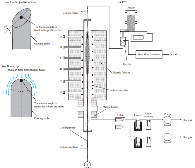
Figure 5 is a schematic of the DTF. The DTF consists of a feeder, electric furnace with a reaction tube, mantle heater, and cooling probe. Pulverized fuel is ejected at a fixed rate by the feeder, sucked together with air by the ejector, and fed to the reaction tube (total length: 2 000 mm, temperature measuring seats: A to F). In the reaction tube, the heating temperatures of the electric furnace and the mantle heater were controlled so as to simulate the temperature distribution from the burner to the rear heat transfer section. The cooling probe was inserted from the bottom into a position where the required furnace temperature could be reached, and the surface temperature was controlled based on the flow rate of the air fed into the probe. To evaluate the effects of the flow field, two types of probes were used: one with a flat tip, and the other with a round tip. In these tests, the cooling probes were exposed to the combustion atmosphere for 5 hours to allow ash to deposit on the probe tips, and the deposited ash was sampled by brush after pulling out the probes from the furnace and cooling them. The thickness of the ash deposited on the probes was 1 mm or less, which means that the deposition obtained with the DTF is equivalent to the initial ash deposition.
3.3 Results and discussion
3.3.1 Ash deposition behavior
Figure 6 shows the ash deposition behavior of each fuel observed with a video camera from the inspection window of the horizontal furnace at each furnace temperature as well as the condition of ash deposited on the water cooling tube. With regard to Wood Pellet A, the deposited ash did not detach at any furnace temperature during 300-minute exposure, and did not melt according to visual observation. With regard to Wood Pellet B, the deposited ash did not detach at any furnace temperature during 300-minute exposure, but the ash did melt. With regard to the agricultural residue pellet, the ash melted and deposited widely in the circumferential direction on the water cooling tube. Wood Pellets A and B and the agricultural residue pellet had ash deposited more widely in the circumferential direction on the water cooling tube than bituminous coal. Although the details are described in Section 3.3.4, this is presumably because biomass contains more alkaline components than coal, and when the vapor of chloride and other substances formed by these alkaline components is condensed, ash is deposited widely in the circumferential direction even where the collision angle is large and ash particles are unlikely to deposit.
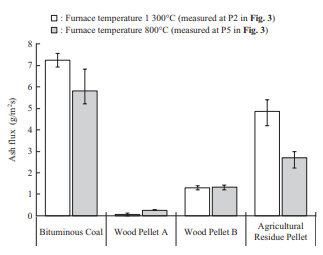
The concentration of fly ash in flue gas was measured as an ash flux, or the weight of ash that passes per unit time or projected cross-sectional area, by inserting an L-shaped silica tube into the furnace and sampling the ash particles for a certain period by means of isokinetic sampling. Figure 7 shows the results of ash flux measurement in the horizontal furnace. Biomass has a lower ash than coal, so it accordingly has a smaller ash flux. In particular, the ash flux of wood pellets is equivalent to or less than one-fifth that of bituminous coal. Although the details are described in Section 3.3.2, the ash deposition ratio of Wood Pellet A exhibits the same behavior as that of bituminous coal across the entire temperature range, which means that depending on the ash flux, the amount of ash deposited for Wood Pellet A is less than that of bituminous coal.
3.3.2 Ash deposition ratio
The degree of ash deposition was calculated by the ash deposition ratio (D) defined by Equation (1)(10)
D = 100·A/C ···························· (1)
C = F·T·P ······························· (2)
F : Ash flux (g/m2·s)
A : Amount of ash deposited (g)
T : Probe exposure time (s)
C : Amount of ash that collides with the water cooling tube (g)
P : Projected cross-sectional area of the water cooling tube (m2)
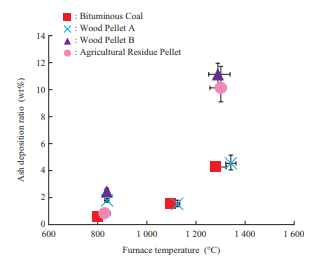
Figure 8 shows the ash deposition ratio obtained in the horizontal furnace test. Regarding the ash deposition ratio as temperature varies, bituminous coal and Wood Pellet A exhibit the same tendency. Under the furnace conditions (1 300°C atmosphere), Wood Pellet B and the agricultural residue pellet have a higher ash deposition ratio than bituminous coal and Wood Pellet A, which means that ash deposits more easily with Wood Pellet B and the agricultural residue pellet.
3.3.3 Ash shedding behavior
Figure 9 shows ash shedding behavior in the test using the air blower shown in Fig. 4.
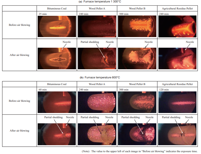
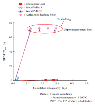
Figure 10 shows the relationship between the cumulative ash quantity and the PIP. This compares the injection pressure and ash quantity during the test. In Fig. 10, the PIP is indicated as a ratio relative to the PIP at coal single firing. From Fig. 10, it can be seen that biomass requires a higher PIP than coal for ash to detach. As for Wood Pellet A, ash detached over the entire temperature range when air was blown with the air blower. Over the entire temperature range, the ash that detached was limited to that around the injection nozzle. This is presumably because for Wood Pellet A, ash was deposited in the powder layer without melting, and due to the low bonding strength of the deposited particles, it detached in only the area where air was blown.
As for Wood Pellet B and the agricultural residue pellet, ash did not detach at a furnace temperature of 1 300°C. What allows ash to detach are the use of an external force (e.g., air blowing) to increase the stress acting on the ash as well as decreasing the deposition area and bonding strength between particles(11). However, with biomass fuels such as Wood Pellet B, which has fuel properties according to which chloride deposits easily (to be described in Section 3.3.4) and the agricultural residue pellet, which has a low ash fusion temperature ash does not detach easily because it melts and deposits widely as well as has a high bonding strength between particles. In such cases, multiple measures must be taken, such as adding an additive or co-firing such a fuel with another fuel in order to prevent chloride from depositing and increase the ash fusion temperature applying coating to the boiler tube to decrease the adhesion force, and improving the soot blower.
3.3.4 Chloride deposition behavior
- - Chloride deposition mechanism
- Figure 11 shows the SEM-BSE (Scanning Electron Microscope-Backscattered Electron) images and the EDS (Energy Dispersive X-ray Spectroscopy) mapping results for the cross section of deposited ash of Wood Pellet B sampled in the horizontal furnace test. The figure shows that angular potassium chloride (KCl) crystals deposit and accumulate.
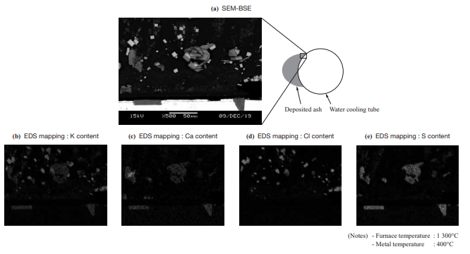
Figure 12 shows the K content behavior obtained by thermodynamics equilibrium calculation. KCl turns from a gas into a solid at 600 to 800°C. In other words, it is presumed that at a metal temperature of 650°C or less, KCl vapor was condensed on the surface of the water cooling tube.
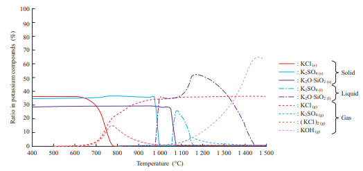
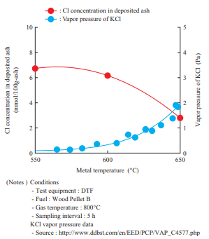
Figure 13 shows the effects of the metal temperature on the Cl concentration in the deposited ash. This shows the results of Cl concentration measurement in the ash sampled at different metal temperatures during the DTF test. The Cl concentration in the deposited ash in Fig. 13 indicates the value obtained by measuring Cl as a water-soluble component. This result found that as the metal temperature increases, the vapor pressure of chloride around the water cooling tube (Figs. 3 and 4) and/or cooling probe (Fig. 5) increases and the vaporized chloride does not condense easily, thereby causing chloride deposition to decrease. These results are consistent with the study results that have been reported thus far(12).
- - Effects of the flow field around the water cooling tube
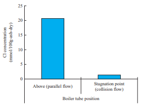
- In the horizontal furnace test, ash was sampled at the stagnation point, where the gas flow is a collision flow, and a point above the water cooling tube, where the gas flow is a parallel flow, as shown in Fig. 2-(a). Figure 14 shows the Cl concentration in the ash deposited in the flow field around the water cooling tube. This figure shows the differences in Cl concentration in the deposited ash between the stagnation point and the point above the water cooling tube. Note that the Cl concentration above the water cooling tube, where the gas flow is a parallel flow, is higher. This is presumably due to the effect of the flow field around the water cooling tube. Cl is deposited when chloride vapor condenses, but silicon (Si) and aluminum (Al) are deposited when solid ash particles collide with the probe; therefore, it is presumed that above the probe, where the gas flow is a parallel flow, colliding particles slip and the deposition after vapor condensation becomes dominant. However, at the stagnation point of the water cooling tube, both deposition after vapor condensation and deposition of ash particles occur, and the components to be condensed are diluted. Therefore, the differences in Cl concentration are presumed to be caused by the flow around the water cooling tube. These results indicate that the chloride deposition phenomenon caused by the flow field around the water cooling tube can be explained by the condensation mechanism.
- - Measures to suppress chloride deposition
- Chloride deposition can be suppressed by preventing chloride vapor deposition according to the chloride deposition mechanism. Figure 15 shows the relationship between the fuel properties and Cl concentration in the deposited ash. The Cl concentration in the deposited ash in the figure is the value obtained by measuring Cl as a water-soluble component, and the fuel properties were adjusted by changing the fuel or adding additives. Figure 15 shows that the data obtained in the horizontal furnace tests and that obtained in the DTF tests have the same tendency, but the Cl concentration in the deposited ash in the DTF test is lower than that in the horizontal furnace test. Because chloride is deposited when chloride vapor condenses, it is presumed that the Cl concentration in the deposited ash depends on the concentration and temperature gradient in the fluid film formed on the surface of the boiler tube. This means that the Cl concentration in the deposited ash in the DTF test is lower than that in the horizontal furnace test presumably because the flue gas velocity differs greatly between the horizontal furnace (4 to 6 m/s) and the DTF (0.1 to 0.2 m/s) and because a thicker fluid film was formed in the DTF test.
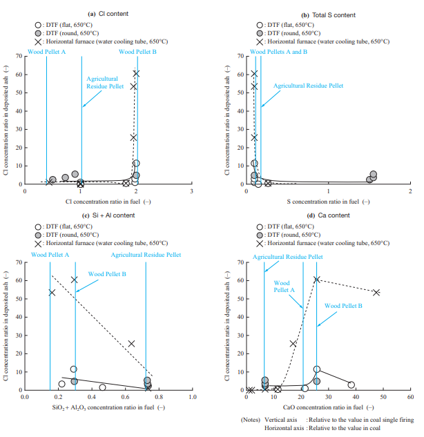
From Fig. 15, it can be seen that chloride deposition occurs when the Cl content in the fuel exceeds a certain level. In addition, it was found that total sulfur (Total-S) and SiO2 + Al2O3 are factors that suppress chloride deposition. It has been reported that, as expressed by Equations (3) and (4), Total-S and SiO2 + Al2O3 react with chloride, and as a result, the Cl content is emitted as hydrogen chloride (HCl) into the gas(9). The obtained result is consistent with the literature. Regarding Ca, it was confirmed that, as expressed by Equation (5), CaO and HCl are factors that increase chloride deposition(13). As shown in Fig. 15, it is presumed that Wood Pellet B has fuel properties which cause Cl to be deposited easily with all of these components — Cl, Total-S, SiO2 + Al2O3, and CaO — and therefore has a wider ash deposition area due to Chloride deposition. Judging from these results, it is effective to select a fuel with a low Cl content and high S and SiO2 + Al2O3 content, to add additives, and to co-fire a biomass fuel with another biomass fuel.
2KCl (or NaCl)(g) + SO2(g) + 1/2O2(g) + H2O(g)
→ K2SO4 (or Na2SO4)(s) + 2HCl(g) ↑ ··························· (3)
2KCl(g) + Al2O3·2SiO2(s) + H2O(g)
→ K2O·Al2O3·2SiO2(s) + 2HCl(g) ↑ ······························· (4)
CaO(s) + 2HCl(g) → CaCl2(s) + H2O(g) ······························ (5)
4. Effects of deposited ash on tube corrosion
4.1 Purpose
The ash deposited on the boiler tube of a biomass single fired boiler contains more alkali chloride than the ash deposited on the boiler tube of a coal-fired boiler(14). There are reports on high-temperature corrosion caused by deposited ash containing chloride, many of which relate to waste incineration boilers(15). However, the corrosion behavior of biomass single fired boilers, which have a higher boiler tube temperature, is thought to differ from that of waste incineration boilers. In addition, the fuel gas composition and deposited ash composition differ greatly depending on the biomass type and boiler tube temperature. In order to evaluate the high-temperature corrosion characteristics of materials in biomass combustion, there is a need to clarify in advance the relationship between combustion conditions and deposited ash composition. Therefore, we conducted ash deposition tests using a horizontal furnace under various conditions, including biomass type, mixing ratio in co-firing with coal, and additives. Based on the ash analysis results, we blended reagents to prepare simulated ash and used it to conduct a high-temperature corrosion test.
4.2 Test facilities
We evaluated the corrosion characteristics of the material by conducting a high-temperature corrosion test in which a test piece was corroded by heating it in an electric furnace. Figure 16 is a schematic of the corrosion test facility that uses an electric furnace. The facility is structured so that a test piece is heated by the electric furnace while supplying a gas with adjusted composition.
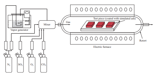
In the high-temperature corrosion test, the simulated ash was applied over the material test piece to be evaluated, which was put into the electric furnace and heated while supplying the gas. In the middle of the test, the simulated ash was applied again and the test piece was heated for a total of 500 hours. After that, the weight decrease of the test piece was measured, and in addition, the average corrosion depth of each sample was measured by observing their cross sections with a microscope. In addition, we evaluated corrosion under various conditions based on the ratio of the corrosion depth to the corrosion depth obtained under conditions simulating coal firing.
4.3 Test results and discussion
As a corrosion test result, Fig. 17 shows the relationship between the relative ratio of the corrosion depths of KA-STBA28, which is 9%-chromium (Cr) steel, and Alloy622 overlay which is a nickel (Ni)-based alloy, under varying deposited ash conditions, including the biomass mixing ratio, in the oxidation gas atmosphere at 600°C (when the corrosion depth of KA-STBA28 under conditions simulating coal single firing is 1) and the Cl concentration in ash(16). The corrosion depth of the KA-STBA28 material increases as the Cl concentration in ash increases. On the other hand, the Alloy622 overlay has high corrosion resistance, and its corrosion depth, even under conditions in which the Cl concentration in ash is high, is smaller than that of KA-STBA28 under conditions simulating coal single firing. This test result indicates that when a biomass fuel that causes a high Cl concentration in ash is burned, the corrosion depth increases, but corrosion can be suppressed by taking measures such as adopting a Ni-based alloy overlay. This result also shows that even in biomass single firing, if the Cl concentration in the deposited ash is low, the corrosion depth does not differ greatly from the corrosion depth under coal single firing conditions.
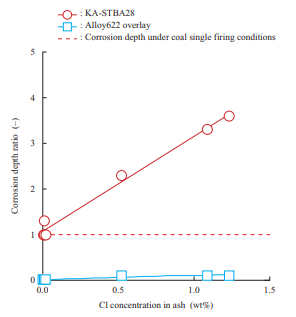
(Average corrosion depth of Ka-STBA28 with coal ash = 1)
Coal ash corrosion in coal-fired boilers is caused by the formation of molten iron alkali sulfate on the boiler tube surface due to the high partial pressure of SOx in the combustion gas(17). In the case of biomass single firing, however, the partial pressure of SOx is low and no iron alkali sulfate is formed. It is presumed that corrosion is accelerated mainly by the formation of molten salt made up of alkali chloride and sulfate in the deposited ash as well as the breakage of the iron (Fe) and Cr oxide layers by Cl generated by the decomposition of alkali chloride(18).
5. Conclusion
This paper introduced measures taken against ash deposition and corrosion, which is a challenge to overcome in order to realize biomass single fired boilers. We clarified the ash deposition mechanism while focusing on the condensed phase of chloride compounds and we clarified the measures for it. We also clarified its corrosion characteristics and corrosion mechanism.
Biomass single fired boilers will continue to be used because they use carbon-neutral fuels. The IHI Group will accumulate more data on new biomass fuels in order to contribute to the stable operation of biomass single fired boilers. Also, in combination with technologies to capture CO2 by means of chemical absorption(19), (20) and oxyfuel combustion(21), the IHI Group will realize the capture, utilization, and storage of CO2 from biomass fuel, thereby achieving a carbon negative status.
Amid the accelerating social trends toward decarbonization by 2030 and then 2050, the IHI Group will contribute to stable electricity supply and CO2 emissions reduction using biomass.
— Acknowledgments —
The results of the ash deposition test and the corrosion test with varying biomass mixing ratios shown in this paper are based on results obtained from a project, JPNP16002, commissioned by the New Energy and Industrial Technology Development Organization (NEDO). We would like to express our gratitude here.
REFERENCES
(1) IHI Corporation : IHI Receives 20-Year Order to Construct and Provide Operation and Maintenance Services for Carbon-Neutral Biomass Power Plant, < https://www.ihi.co.jp/en/all_news/2020/resources_energy_environment/1197371_2032.html >, accessed 2021-03-31
(2) M. Tamura, S. Watanabe, Y. Kubota, K. Komaba, N. Kotake and M. Hasegawa : Experimental Analysis on Grinding Characteristics of Woody Biomass, The Thermal and Nuclear Power, Vol. 63, No. 2, 2012, pp. 109-113
(3) H. Kasai, H. Fukushima, M. Tamura, K. Inubushi and T. Nakata : Meeting the Challenge of Realizing a High Ratio Co-Firing System with Woody Biomass, IHI ENGINEERING REVIEW, Vol. 54 No. 2, 2021 (4.4MB)
(4) J. Shigeta, K. Chie : Behavior of Ash Deposition at Coal Fired Boiler, IIC REVIEW, No. 55, 2016, pp. 21-29
(5) E. Raask : Mineral Impurities in Coal Combustion, Hemisphere Publishing Corporation, 1985
(6) G. Couch : Understanding Slagging and Fouling during Pf Combustion, IEA Coal Research, 1994
(7) S. Mori, J. Shigeta, K. Suzuki and H. Fukushima : Study of Slagging Index at Pulverized-Coal Combustion Boiler, Ishikawajima-Harima engineering review, Vol. 45 No. 1, 2005, pp. 36-41
(8) S. V. Loo and J. Koppejan : The Handbook of Biomass Combustion & Co-firing, Routledge, 2010
(9) R. A. Antunes and M. C. L. Oliveira : Corrosion in biomass combustion: A materials selection analysis and its interaction with corrosion mechanisms and mitigation strategies, Corrosion Science, Vol. 76, 2013, pp. 6-26
(10) I. Naruse, D. Kamihashira, Khairil, Y. Miyauchi, Y. Kato, T. Yamashita and H. Tominaga : Fundamental ash deposition characteristic in pulverized coal reaction under high temperature conditions, Fuel, Vol. 84, Iss. 4, 2005, pp. 405-410
(11) N. Sato, S. Ueno, E. Ohno, M. Tamura, Y. Ueki, R. Yoshiie and I. Naruse : Effects of mechanical stresses around single tube on ash shedding in pulverized coal combustor, Proceedings of the Combustion Institute, Vol. 37, Iss. 3, 2019, pp. 2 875-2 882
(12) X. Jin, J. Ye, L. Deng and D. Che : Condensation Behaviors of Potassium during Biomass Combustion, Energy Fuels, Vol. 31, No. 3, 2017, pp. 2 951-2 958
(13) Y. Zheng, P. A. Jensen, A. D. Jensen, B. Sander and H. Junker : Ash transformation during co-firing coal straw, Fuel, Vol. 86, Iss. 7 - 8, 2007, pp. 1 008-1 020
(14) P. J. Henderson, P. Ljung, T. H. Eriksson, S. B. Westberg, B. Hildenwall, T. Abyhammar : Corrosion Testing of Superheater Steels for Biomass-Fired Boilers and the Effects of Co-Firing with Coal, Advanced Materials for 21st Century Turbine and Power Plant: Proceedings of the Fifth International Charles Parsons Turbine Conference, 2000, pp. 1 094-1 104
(15) Y. Kawahara, N. Orita, K. Takahashi and Y. Nakagawa : Demonstration Test of New Corrosion-resistant Boiler Tube Materials in High Efficiency Waste Incineration Plant, Tetsu-to-Hagané, Vol. 87, No. 8, 2001, pp. 544-551
(16) IHI Corporation : Working paper on “Behavior elucidation and measures of the various biomass ash deposition on the boiler tube in coal power generation”, a project in 2018-2019, JPNP16002, commissioned by the New Energy and Industrial Technology Development Organization, 2020
(17) W. Nelson and C. Cain Jr. : Corrosion of Superheaters and Reheaters of Pulverized-Coal-Fired Boilers, Journal of Engineering for Gas Turbines and Power, Vol. 82, Iss. 3, 1960, pp. 194-201
(18) Y. Kawahara : High temperature corrosion mechanisms and effect of alloying elements for materials used in waste incineration environment, Corrosion Science, Vol. 44, Iss. 2, 2002, pp. 223-245
(19) T. Endo, H. Kamata, K. Nariai : Carbon Capture and Utilization Technology, Energy, Journal of the Japan energy association, No. 294, pp. 49-54
(20) H. Tomita : Development of CO2 Capture and Utilization Technology Toward Achievement of Carbon Recycling Society, The thermal and nuclear power, Vol. 71, No. 4, 2020, pp. 926-930
(21) C. Spero and T. Yamada : Callide Oxyfuel Project-Final Results, Global CCS Institute, < https://www.globalccsinstitute.com/resources/publications-reports-research/callide-oxyfuel-project-final-results/ >, accessed 2021-03-31