Co-Generation Power Plant with High-Efficient Spark Ignition Lean-Burn Gas Engine 28AGS for Reduction of CO2 Emissions
KUROIWA Takanori, ASATO Kenya, ANDO Kazunori, MATSUYAMA Yoshimitsu

KUROIWA Takanori : RE Design & Development Department, Engineering & Technology Center, IHI Power Systems Co., Ltd.
ASATO Kenya : Plant Engineering Department, Power System Plants Business Division, IHI Power Systems Co., Ltd.
ANDO Kazunori : Senior Engineer, Plant Engineering Department, Power System Plants Business Division, IHI Power Systems Co., Ltd.
MATSUYAMA Yoshimitsu : Principal Engineer, Turbomachinery & Machine Elements Group, Technology Platform Center, Technology & Intelligence Integration
IHI Power Systems Co., Ltd. has supplied co-generation systems equipped with a gas engine to various sites. The spark ignition lean-burn gas engine 28AGS is a main model in late years. This model has features that it is highly efficient and emits a smaller amount of CO2, a greenhouse gas, with stabilization technology for combustion with the lean air-fuel mixture. In 2020, the gas engine co-generation system, which was composed of the gas engine 28AGS and the binary generator manufactured by IHI, was installed at IHI Yokohama Works and the site is expected to reduce CO2 emissions by approximately 1 400 tons/year. This paper introduces the outline of the system.
1. Introduction
The IHI Group has pledged to make its complete value chain carbon-neutral by 2050. We aim to be carbon-neutral in our processes overall by reducing the direct and indirect greenhouse gas emissions from our business activities as well as emissions from the upstream and downstream processes in our value chain. As part of such efforts, IHI Power Systems Co., Ltd. (IPS) delivered a co-generation system (CGS) to the Yokohama Works of IHI Corporation(1). The system packages the 28AGS, a 4 000-kW high-efficiency gas engine, with a binary generator that generates electricity using heat from the gas engine’s cooling water. This CGS power plant was designed in consideration of saving energy, reduction of CO2 emissions (a cause of global warming), and disaster prevention. This paper gives an overview of this CGS power plant and the measures in place there.
2. Market situation and background to the introduction of CGS
2.1 CGS
CGS is an energy supply system that recovers power and heat using waste heat (e.g., heat from internal combustion engines and external combustion engines) to enhance total energy efficiency. With CGS, electricity can be generated near the point of demand, reducing energy loss in power transmission. CGS is attracting attention because the amount of energy discarded without being used effectively when electricity is generated for commercial power supply can be reduced by replacing part of electricity purchased from commercial power suppliers and part of the demand for electrical heat covered mainly by boilers with CGS.
In addition, with an energy management system (EMS), the operational data of power generation facilities and detailed power consumption data can be collected and visualized, thereby contributing to further CO2 emissions reduction achieved by power savings and demand optimization.
2.2 Features of gas engines
One major feature of gas engines is that they have clean flue gas properties. Compared to liquid fuels (e.g., petroleum), natural gas, which is a fuel for gas engines, emits less nitrogen oxide (NOx), sulfur oxide (SOx), soot and other fuel-derived hazardous substances generated by combustion. Methane (CH4), which is a primary component of natural gas, has a high hydrogen (H2) content in relation to the carbon (C) content in fuel; therefore, use of natural gas can reduce the amount of fuel-derived CO2 emissions generated by combustion. In addition, natural gas is very environmentally compatible because NOx emissions, which cause photochemical smog and acid rain, can be reduced by lean combustion.
The reserve-production ratio of natural gas has increased thanks to the development of shale gas. Gas engines can be economically advantageous because of the price difference between liquid fuel and gas fuel; therefore, expectations for CGS using gas engines are increasing.
3. Overview of the CGS power plant
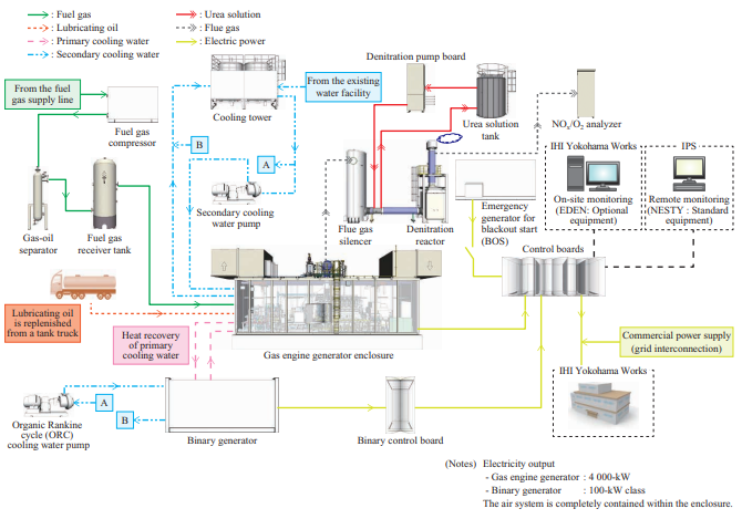
Figure 1 shows the system flow of the CGS power plant at IHI Yokohama Works. The CGS power plant has six systems: primary cooling water, secondary cooling water, lubricating oil, fuel gas, air (not released into the environment), and flue gas. The following is a system overview of the facility.
3.1 System overview of the facility
3.1.1 Cooling system
Primary cooling water and secondary cooling water are used to cool the gas engine. These are separated from each other. Primary cooling water is used to cool the gas engine, and is then in turn cooled by the secondary cooling water through the heat exchanger before being recirculated to cool the gas engine again. The lubricating oil is also cooled by the secondary cooling and automatically controlled to an appropriate temperature. Secondary cooling water, after being used to cool the primary cooling water and lubricating oil by heat exchange, is sent to the cooling tower, where heat is radiated by heat exchange with the atmosphere by the cooling tower fan.
3.1.2 Lubricating oil system
The gas engine and generator base serve as a lubricating oil pan (hereinafter, a lubricating oil sump tank). Lubricating oil is supplied from the lubricating oil sump tank to each sliding part by the pump. In addition, a lubricating oil purification system (LUBCLIN made by IPS) is used to purify the lubricating oil in the lubricating oil sump tank by means of by-pass purifying, thereby extending the lifetime of the lubricating oil. At the time of replenishment, lubricating oil can be supplied directly into the lubricating oil sump tank from a tank truck.
3.1.3 Fuel gas supply method
Fuel gas is supplied from a non-industrial city gas line and sent to the gas engine after being regulated to the specified pressure by a fuel gas compressor. The pressurized fuel gas contains lubricating oil components (hereinafter, oil content), and if fuel gas with high oil content is sent to the gas engine, the solenoid valve for regulating the fuel gas flow rate may become stuck. To prevent this, oil content is reduced by a gas-oil separator before sending fuel gas to the gas engine.
3.1.4 Air system
Within the enclosure, an air compressor and a starting air tank are installed on the auxiliary unit, and an instrument air compressor is installed on the inspection platform. The compressed air generated by the air compressor is stored in the starting air tank and used to start the gas engine. The compressed air generated by the instrument air compressor is used to operate the instruments.
3.1.5 Flue gas treatment method
A flue gas silencer is used to reduce the noise generated by flue gas from the gas engine. After the noise level is reduced, the flue gas passes through the denitration reactor, where the amount of NOx in the flue gas is reduced, and is then released into the atmosphere (the details of the denitration reactor are described in Section 5.2).
3.1.6 Monitoring system
A power generation monitoring system called EDEN® (Electric Diesel Engine Network, optional) is installed to continuously record the temperature and pressure of each system of the CGS power plant. The information is sent through the Internet to IPS’s centralized monitoring system NESTY (Niigata Engine SupporT sYstem, standard equipment) to allow IPS to continuously monitor the gas engine, thereby realizing a customer support system.
3.1.7 Blackout start (BOS) function
This power plant is provided with an emergency generator for BOS so that power can be supplied to the auxiliaries in order to start the gas engine even if a commercial power failure occurs.
3.1.8 Binary generator
This power plant is provided with a binary generator to generate electricity using waste heat from the gas engine’s primary cooling water for energy reuse (the details of the binary generator are described in Section 5.1).
3.2 Features of the CGS power plant
The major features of the CGS power plant at IHI Yokohama Works are as follows:
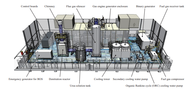
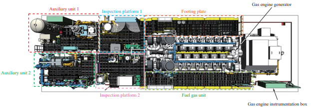
- Space savings: As the layout in Fig. 2 shows, this CGS power plant has been installed compactly. In addition, the gas engine generator and a set of integrated auxiliaries are installed in the enclosure, thus contributing to space savings. Figure 3 shows the layout of the enclosure interior.
- Highly environmentally-compatible CGS facilities feature systems for reducing CO2 by energy conservation and NOx contained in flue gas.
- As a disaster-resistant facility, that has a countermeasure to the tsunami and backups for power failures. It contributes to business continuity planning (BCP).
- Measures against tsunami: The generator enclosure foundation and auxiliary mounts are installed at a height of 2 m above ground level.
- Backups for power failures: An emergency generator for BOS is provided in the event of a disaster.
- Facility efficiency is enhanced through energy reuse with a binary generator.
4. Gas engine generator
4.1 Gas engine 28AGS for power generation
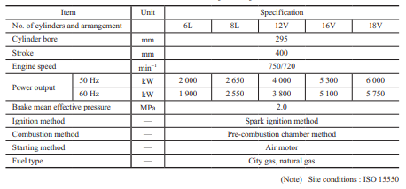
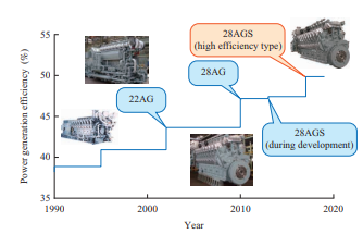
The gas engine 28AGS, for which development was completed in 2012, is a spark ignition lean-burn gas engine that ignites an air-fuel mixture in the pre-combustion chamber with a sparkplug and burns a lean air-fuel mixture in the main combustion chamber with a flame jet from the pre-combustion chamber. Table 1 shows the lineup and engine specifications of the 28AGS series.
The 28AGS series is attracting attention because of its high performance and advanced disaster resistance. The series has the following features.
- World’s highest level of power generation efficiency in this engine class
- High load response characteristics with optimized air-fuel ratio control
- High startability and capability to build up voltage within 40 seconds of startup
- Equipped with an important load survival operation (function to disconnect commercial power supply in the event of a power failure and to continue power generation), which makes it possible to continue to feed power to critical loads and contributes to BCP
4.2 Efforts to increase gas engine thermal efficiency
In 2017, making the most of the accumulated technical knowledge, IPS successfully enhanced the efficiency of the 28AGS series while maintaining the aforementioned excellent features. Figure 4 shows the history of efficiency enhancement of IPS gas engines. The first model of the high-efficiency 28AGS series has been operating in multiple fields since the shipment in June 2020.
This CGS power plant adopted the V-type, 12-cylinder gas engine 28AGS, whose efficiency was enhanced through this development to the highest level in its class.
The following describes some of technologies applied to enhance the thermal efficiency of the 28AGS series.
4.2.1 Optimization of the flame jet from the pre-combustion chamber to the main combustion chamber
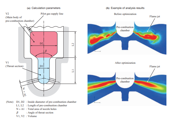
The spark ignition method with a pre-combustion chamber, which was adopted for the 28AGS series, uses discharge sparks from a sparkplug as an ignition source. Gas fuel is supplied directly into the pre-combustion chamber and mixed with air from the main combustion chamber to form a nearly stoichiometric air-fuel mixture in the pre-combustion chamber. This nearly stoichiometric air-fuel mixture is ignited by the sparkplug and burned. After that, hot gas is injected into the jet flow of the main combustion chamber (flame jet) to burn a lean air-fuel mixture in the main combustion chamber. Therefore, optimizing this flame jet is essential to achieve stable combustion. For this reason, we studied and evaluated the shape of the pre-combustion chamber using CFD (Computational Fluid Dynamics) simulation in order to optimize the flame jet(2).
Figure 5 shows the results of CFD analysis of the flame jet from the pre-combustion chamber. This is an example of the calculation parameters of the pre-combustion chamber shape and the analysis results of the flame jet before and after shape optimization. Before shape optimization, the flame jet has low straightness and a short reaching distance. After shape optimization, the flame jet has higher straightness and a longer reaching distance. This makes it possible to burn even a lean air-fuel mixture around the cylinder liner wall distant from the center of the main combustion chamber. The optimized pre-combustion chamber shape was verified with a test engine and confirmed to have an effect of reducing variation in combustion in the main combustion chamber. As a result, the maximum firing pressure in the main combustion chamber could be increased without exceeding the maximum permissible firing pressure, thereby enhancing power generation efficiency.
4.2.2 Reduction of unburned gas fuel emissions (methane slip)
In addition to enhanced efficiency, the high-efficiency gas engine 28AGS can reduce unburned gas fuel emissions. This contributes to reducing greenhouse gas emissions and improving environmental compatibility. The gas engine 28AGS mixes air and gas fuel in the intake port and supplies the air-fuel mixture to the main combustion chamber. Methane slip results when air-fuel mixture that has flowed into small gaps in the combustion chamber, such as a crevice between the cylinder head and cylinder liner, does not burn due to excessive heat loss on the combustion chamber wall and is discharged unburned in the exhaust stroke. Thus we verified with a test engine model that methane slip could be reduced by approximately 40% compared to during gas engine 28AGS development by reducing the volume of the small gaps, which may cause unburned gas, in the combustion chamber(2).
4.2.3 Other technologies for efficiency improvement
We have achieved the highest level of efficiency in the engine’s class by combining and optimizing the following technologies as well as the aforementioned element technologies.
- Reducing knocking with homogenized mixture concentration
- Ensuring stable combustion with an optimized air-fuel ratio controller
- Reducing mechanical loss and cooling loss
5. CGS facilities compatible to the air environment
To reduce CO2 emissions and to improve environmental compatibility by saving energy, for this CGS power plant we adopted a binary generator, which uses waste heat from the gas engine to generate electricity, and a denitration facility, which purifies the flue gas. The following describes the system and features of these facilities.
5.1 Binary generator
A binary generator uses low-temperature waste heat (e.g., from the gas engine’s primary cooling water) to generate electricity. The waste heat, which is usually discarded by heat exchange with the secondary cooling water, can be utilized as the heat source of the generator. Adoption of a binary generator has enhanced total efficiency of the entire CGS power plant and reduced the CO2 emissions per kW·h generated by the gas engine.
5.1.1 Principle and system configuration
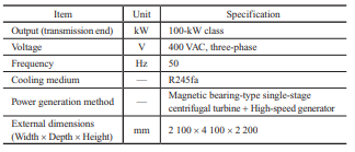
Figure 6 shows the system configuration of the binary generator. The binary generator consists of a circulating pump, evaporator, turbine generator, and condenser, which are packaged into a single unit, thereby facilitating installation. This system adopts the organic Rankine cycle (ORC), by which a medium with a low boiling point is heated and evaporated to generate electricity with a turbine.
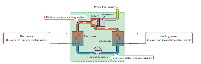
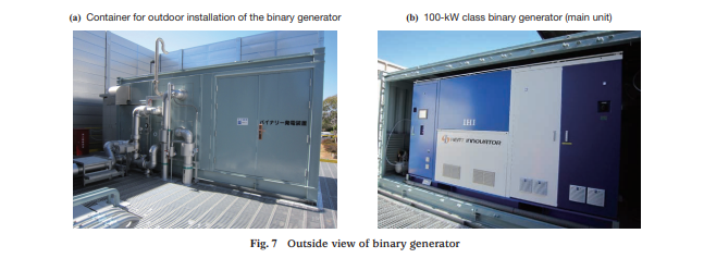
The low-temperature liquid cooling medium is pressurized by the circulating pump, sent to the evaporator, and heated and gasified by heat exchange with the primary cooling water at a temperature of approximately 90°C (when the engine load is 100%) to form cooling medium steam. The high-pressure cooling medium expands in the turbine, is cooled and condensed by heat exchange with the secondary cooling water of the gas engine, and returns to the original low-temperature cooling medium. All components are housed in the package, which can be used only by connecting the primary and secondary cooling water. This realizes the simple appearance shown in Fig. 7.
5.1.2 Capacity of the binary generator
This CGS power plant adopted a binary generator manufactured by IHI. The major specifications are listed in Table 2.
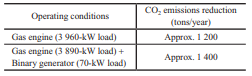
When the gas engine is operated alone and operated with the binary generator for 24 hours, CO2 emissions are significantly lower than when purchasing electricity from an electrical utility as is done conventionally. Table 3 lists the CO2 emissions reduction of IHI Yokohama Works. When the gas engine is used with the binary generator, CO2 emissions are lower by approximately 200 tons annually than when the gas engine is used alone.
5.2 Denitration facility
A denitration facility is a set of devices for reducing NOx in flue gas from a gas engine. It consists of a denitration reactor, urea solution tank, denitration pump board, urea solution injector, and NOx/O2 analyzer. NOx in flue gas can be broadly classified into nitrogen monoxide (NO) and nitrogen dioxide (NO2), and most NOx generated in the combustion is NO. After being released into the atmosphere, NO reacts with ozone and other substances to form NO2, which is a hazardous substance. Denitration facilities use a chemical reaction process to reduce NO in flue gas to nitrogen (N2) and water (H2O) for detoxification before the flue gas is released into the atmosphere (hereinafter, the denitration reaction).
This CGS power plant uses a gas engine with a denitration facility in order to reduce NOx while maintaining the gas engine’s efficiency, thereby reducing NOx through the denitration reaction using a urea-reducing agent and improving environmental compatibility.
5.2.1 Principle and system configuration
Figure 8 shows the denitration reaction process. In the denitration facility, urea solution is sprayed in the form of mist into the flue gas with a urea solution injector and reacted with NOx in the flue gas. This reaction consists of the following two steps.
(1) Urea solution decomposition/ammonia generation(4)
After being sprayed into the flue gas, the urea solution is heated by the high-temperature flue gas at a temperature of 300 to 450°C and undergoes the following two decomposition reactions to generate ammonia (NH3).
Pyrolysis : (NH2) 2CO → NH3 + HNCO ···························· (1)
Hydrolysis : HNCO + H2O → NH3 + CO2
(2) NOx selective reduction reaction(4)
The NH3 obtained by the pyrolysis reaction in formula converts NOx (NO or NO2) to N2 and H2O by the following reactions when it passes through the denitration catalyst in the denitration reactor.
4NO + 4NH3 + O2 → 4N2 + 6H2O
2NO2 + 4NH3 + O2 → 3N2 + 6H2O
NO + NO2 + 2NH3 → 2N2 + 3H2O
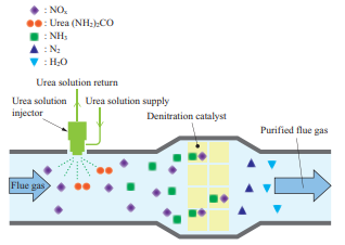
Figure 9 shows the system configuration of the denitration facility. Urea solution is supplied from the tank to the injector with the denitration pump and sprayed into the flue gas pipe. The amount of urea solution sprayed is determined based on the NOx concentration (theoretical value) at the gas engine’s outlet at each load. The NOx concentration at the outlet of the denitration reactor measured by the NOx/O2 analyzer is fed back to the denitration pump board for correction.
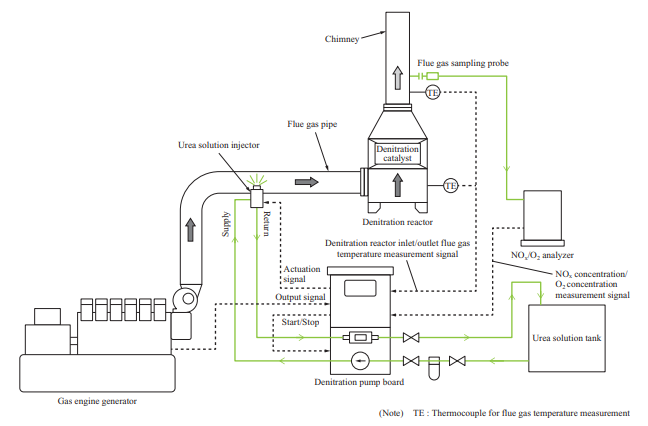
This CGS power plant adopted a denitration facility manufactured by FORECO inc. One feature of this company’s facilities is that part of the urea solution supplied to the urea solution injector is returned to the urea solution tank and recirculated. This provides the following effects.
- The returned urea solution is used to keep the injector below a certain temperature.
- The temperature of the urea solution in the urea solution supply line is lower (200 to 300°C) than that of the urea solution sprayed in the form of mist into the flue gas pipe. Therefore, not all the urea solution decomposes into NH3; some of the urea solution forms water-insoluble substances, such as cyanuric acid and ammelide. The urea solution is circulated so that the injector will not become clogged with these substances. In addition, an injector with a built-in solenoid valve is used, which eliminates the need to use compressed air and cleaning water, which are required by the conventional two-liquid-type air assist nozzle.
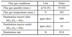
5.2.2 Denitration capacity
Table 4 lists the denitration capacity when the load of this CGS power plant is 100%. The denitration capacity is 92.8% at the flue gas quantity, flue gas temperature, and NOx concentration at the denitration reactor’s inlet, which means that this power plant is sufficiently compatible to the air environment.
6. Conclusion
We have delivered an environmentally compatible, disaster-resistant gas engine CGS power plant to IHI Yokohama Works. By combining a gas engine with a binary generator, this power plant is expected to reduce CO2 emissions from the Yokohama Works by 1 400 tons annually, thereby contributing to the global trend in greenhouse gas emissions reduction.
In addition, this power plant is equipped with a BOS function and is capable of ensuring adequate power supply by means of the gas engine even in the event of a disaster.
CGS power plants using gas engines are environmentally compatible and simultaneously contribute to saving energy; therefore, they are increasingly being introduced at various sites.
IPS will offer high-quality gas engine CGS power plants globally, thereby contributing to achieving carbon neutrality throughout the entire value chain.
REFERENCES
- IHI Corporation : Installation of highly efficient co-generation system with gas engine and binary generator at Yokohama Works — Contribution to enhancement of regional resilience to disaster and reduction of CO2 emissions —, < https://www.ihi.co.jp/ihi/all_news/2019/ resources_energy_environment/1190456_1591.html >, accessed March 2, 2021
- S. Nakayama, T. Kuroiwa, T. Nakazato and T. Saito : Performance Improvement of Spark-Ignited Medium Speed Gas Engine 28AGS, IHI Engineering Review, Vol. 53, No. 1, 2020
- IHI Corporation : Leaflet of 100-kW binary generator — HEAT INNOVATOR —
- FORECO inc. : Instruction manual and system configuration diagram of denitration system with urea solution, pp. 2-3