Demonstration Testing for 1 400°C Class CMC Shroud with JAXA F7 Turbofan Engine
WATANABE Fumiaki, YAMANAKA Shohei, NAKAMURA Takeshi
WATANABE Fumiaki : Manager, Engine Technology Department, Research & Engineering Division, Aero Engine, Space & Defense Business Area
YAMANAKA Shohei : Manager, Engine Technology Department, Research & Engineering Division, Aero Engine, Space & Defense Business Area
NAKAMURA Takeshi : Manager, Materials Technology Department, Research & Engineering Division, Aero Engine, Space & Defense Business Area
Japan Aerospace Exploration Agency (JAXA) introduced F7-10 turbofan engine to demonstrate new aeroengine technologies developed in Japan by producing their usage environment with an actual engine. The engine is a high bypass ratio turbofan engine developed by Acquisition, Technology & Logistics Agency (ATLA) for P-1 maritime patrol aircraft. In the course of its development, IHI designed and manufactured it. Commissioned by New Energy and Industrial Technology Development Organization (NEDO), IHI developed a ceramic matrix composite (CMC) shroud which has 1 400°C class temperature capability and confirmed its soundness when mounted in the actual engine through a demonstration test conducted jointly with JAXA.
1. Introduction
Recently, social demands for the reduction of CO2 emissions are increasing more and more, and efforts to improve the fuel consumption of aeroengines are becoming more and more important. Development is underway also in Japan to develop new technologies for improving the fuel consumption of aeroengines. It requires a very long time and a substantial amount of money to develop a new model. In particular, aeroengines are required to have high reliability, and therefore, introducing a new technology requires verifying its applicability through various tests and reducing risks to an acceptable level. Engine components are used in an environment with a combination of high temperature, load, vibration, and so on, which is unique to actual engines. Therefore, it is essential to conduct testing in an actual engine environment where these conditions can be comprehensively verified.
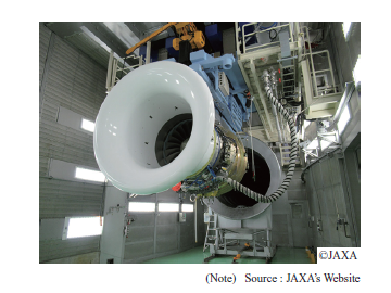
In order to verify new technologies developed in Japan, the JAXA F7 turbofan engine shown in Fig. 1 was introduced in 2019 for technical demonstration testing at the Japan Aerospace Exploration Agency (JAXA)(1). The F7 turbofan engine is a high-bypass ratio turbofan engine developed by the Acquisition, Technology & Logistics Agency (ATLA) for P-1 maritime patrol aircraft. IHI was in charge of designing and manufacturing the F7 turbofan engine. ATLA and IHI concluded a commercial transfer agreement for selling the JAXA F7 turbofan engine to JAXA, and it was introduced into JAXA in 2019. The JAXA F7 turbofan engine is expected to further promote the development of new technologies in Japan.
As an effective method for improving engine fuel consumption, it is expected to reduce the amount of cooling air and increase the turbine inlet temperature by improving the heat resistance of high-pressure turbine components. Conventionally, nickel-based and other superalloys have been used as high-pressure turbine materials. Recently, however, ceramic matrix composites (CMCs) have been put to practical use for greater heat resistance. IHI has been developing CMC materials and components over several decades(2). On consignment from the New Energy and Industrial Technology Development Organization (NEDO) beginning in 2015, we developed a CMC material having 1 400°C class heat resistance, which is the highest level in the world, and a high-pressure turbine shroud using the CMC material. Then in 2021, we conducted a demonstration test with the high-pressure turbine shroud mounted on the JAXA F7 turbofan engine. This paper describes the outline of development of the 1 400°C class CMC shroud and the results of the engine test.
2. CMC material system
Ceramic materials are generally lighter and more heat-resistant than metallic materials, but exhibit brittle fracture behavior. Therefore, it has been difficult to apply ceramic materials to aeroengine components, which are required to have high reliability. CMC is a composite material made of ceramic reinforced with ceramic fibers. Since the propagation of microcracks in the material is hindered by the reinforcement fibers, it exhibits ductile behavior throughout, like in metallic materials, and therefore, can be applied to aeroengine components.
On consignment from NEDO, IHI developed a material system having the following configuration with the aim of developing a material that can withstand use at around 1 400°C. We adopted Hi-Nicalon Type-S from NGS Advanced Fibers Co., Ltd. as a silicon carbide (SiC) fiber, boron nitride (BN) as a fiber interface coating, and a three-dimensional orthogonal weave as the fabric structure. We created a SiC matrix by using the chemical vapor infiltration (CVI) method, and a rare-earth silicate-based matrix by using the melt infiltration (MI) method. After forming into the component shape, an environmental barrier coating (EBC), which consists of a rare-earth silicate-based undercoat and a hafnia-based topcoat, was applied to the surfaces exposed to the mainstream gas.
We acquired various CMC material data, which are necessary to design a high-pressure turbine shroud, through material tests at up to 1 400°C.
3. Design of the CMC shroud
On consignment from NEDO, IHI developed a shroud using 1 400°C class CMC for demonstration testing. Figure 2 shows a cross-sectional view of the entire engine. The demonstration testing described in this paper was intended for the first-stage shrouds of the high-pressure turbine. The turbine shrouds are located on the outer periphery of the turbine blades and have the function of forming a flow path surface of the mainstream gas. As shown in Fig. 3, the turbine shrouds are exposed to high-temperature, high-pressure gas, and receive thermal load, thermal distribution, differential pressure, vibrations, cyclically, and receive impact due to contact with the turbine blades (rubbing). Therefore, the turbine shrouds must be designed so that the required service life is satisfied in such an environment.
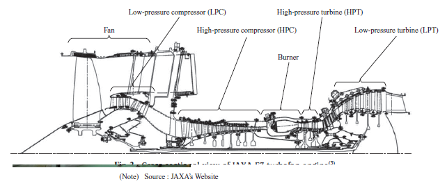
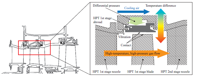
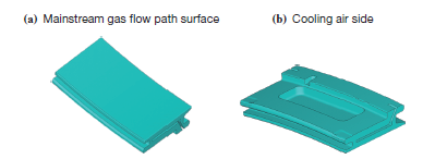
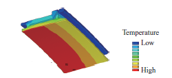
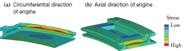
Figure 4 shows the CMC shroud geometry designed so that the above requirement can be satisfied. Figures 5 and 6 show the results of the thermal analysis and stress analysis, respectively. From the analysis results, we confirmed that the maximum design temperature is 1 355°C, and the shroud has sufficient strength for the engine test conditions.
4. Element tests and component tests
IHI developed a 1 400°C class CMC shroud on consignment from NEDO, and conducted the following element tests and component tests (1) to (4) before the engine test:
- (1) High-temperature gas flow exposure test with flat specimens
- (2) Rubbing test simulating contact with the blade
- (3) Strength test of the hook that supports the shroud
- (4) Cyclic thermal test of the shroud
The following describes the outline of tests (3) and (4).
4.1 Hook strength test
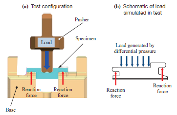
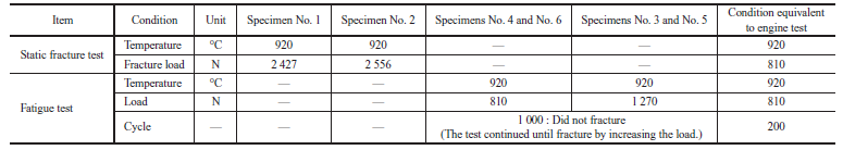
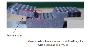
To verify the strength and soundness of the hook that supports the shroud, we conducted a strength test simulating the geometry, engine temperature, and applied load of the actual shroud hook. The test temperature was set to 920°C, which is the temperature of the hook in the engine test estimated by thermal analysis. Figure 7 shows the configuration of the hook strength test. Table 1 lists the test conditions and results. As a result of a static fracture test, we found that the fracture load of two specimens was approximately 2 500 N. In the fatigue test, two specimens did not fracture at 1 000 cycles with a test load of 810 N, which is equivalent to the load generated in the engine test, and two other specimens did not fracture at 1 000 cycles with a test load of 1 270 N, which is more than one and a half times as large as the load generated in the engine test. A load was applied in a stepwise manner to each specimen, and the fatigue test was continued until fracture. Figure 8 shows the appearance of the fractured specimen No. 4 as representative examples. Specimen No. 4 fractured at 13 443 cycles with a test load of 1 490 N. These test results show that the shroud hook has sufficient strength.
4.2 Cyclic thermal test with the actual shroud
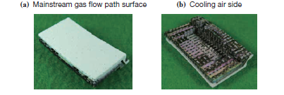
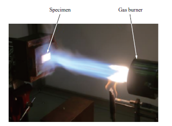
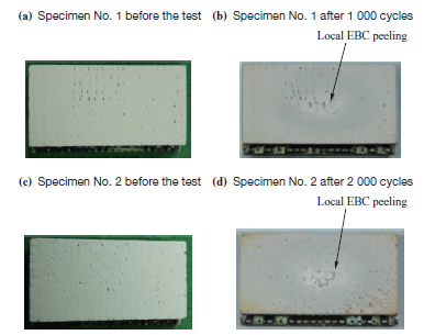
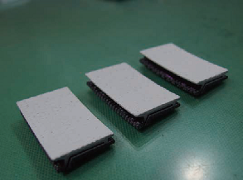
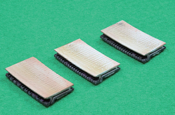
To verify the soundness of the actual shroud against thermal cycling, the shroud was heated repeatedly with a gas burner. Figure 9 shows the CMC shroud before the cyclic thermal test, and Fig. 10 shows the test configuration. The CMC shroud was heated so that the maximum temperature on the mainstream gas flow path surface was 1 400°C and held for about two minutes to cool, repeatedly as a cycle. Figure 11 shows the specimens after 1 000 cycles and after 2 000 cycles. After the test, no damage, except local EBC peeling, was observed on the specimens. The EBC peeled off only locally, which does not affect the functionality of the component even if it occurs in the engine test. We concluded that it would be no problem to proceed to the engine test.
5. Engine test
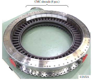
Subsidized by NEDO, IHI conducted a joint demonstration test with JAXA for the 1 400°C class CMC shroud mounted on the JAXA F7 turbofan engine. Figure 12 shows the CMC shroud before the engine test. When the engine test was conducted, 8 out of 32 first-stage shrouds of the high-pressure turbine were replaced with the CMC shrouds. Figure 13 shows the CMC shrouds assembled into a turbine case.
The engine test was conducted at the ground engine test facility in JAXA’s Chofu Aerospace Center (Tokyo) from June to July 2021. The total operation time, including the time during which the engine was maintained at high power and the time during which the engine was accelerated and decelerated, was approximately 80 hours. The test conditions are outlined below:
- Total operation time : Approximately 80 hours
- Time during which the engine was maintained at high power : 37 hours
- Number of startups : 39
- Number of cycles from the idle state to the high power state : 227
- Mainstream temperature at the shroud in the high power state : 1 300°C or more
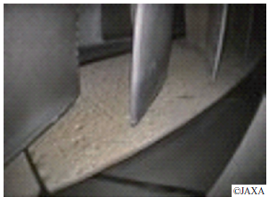
During the operation test, the CMC shrouds and components around them were observed about every 10 hours with borescopes to check for any problems. Figure 14 shows the condition of a CMC shroud observed with a borescope during operation.
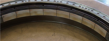
After the engine test, the CMC shrouds were taken out and observed. Figures 15 and 16 show the appearance of the CMC shrouds after the test. After the test, no shrouds or components around them fell off or seized, and the assembly condition remained unchanged from before the engine test. Major results of appearance observation are as follows:
- No damage, such as peeling, was observed on the EBC over the mainstream gas flow path surface.
- The entire surfaces of the shrouds were discolored to brownish red, and a component analysis found that Ca, Mg, Al, Fe, and other substances contained in the mainstream gas adhered.
- No remarkable wear was observed on the areas in contact with adjacent components, such as the hook.
- No damage, such as burnout, chips, and cracks, was observed on the entire surfaces of the shrouds.
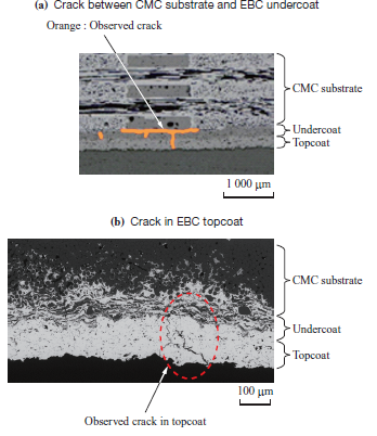
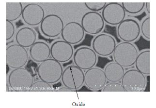
After the engine test, the CMC shrouds were cut to check for changes in the internal condition. Figure 17 shows the microscopic observation result of the cross section of the EBC area. As shown in Fig. 17-(a), a crack was observed on the boundary between the CMC substrate and EBC undercoat. Also, as shown in Fig. 17-(b), a crack was observed in the EBC topcoat. These cracks were determined to have occurred during the engine test. We also observed the microstructure of the inside of the CMC substrate through a microscope. Figure 18 shows the microscopic observation result of the cross section around the shroud surface. No significant changes were observed in the internal microstructure, except some areas near the shroud surface. In some areas around the shroud surface, the BN coating oxidized in the fabric interface.
As above, we checked the condition of the CMC shrouds after the engine test and found that some changes were observed in the appearance and internal structure, but they did not affect the functionality of the shrouds and the shrouds were determined to be still serviceable.
From this engine test, the 1 400°C class CMC shroud was proven to be sound in an actual engine environment.
6. Conclusion
This paper has described the outline of development of the 1 400°C class CMC shroud and the demonstration test of the CMC shroud with the JAXA F7 turbofan engine. We verified the turbine shrouds made of the developed 1 400°C class CMC material by using the JAXA F7 turbofan engine. This enabled us to verify them in an actual engine environment, taking another step forward from component-only verification. To put the CMC shroud into practical use, we will work to verify its long-term durability and improve its manufacturability.
It is expected that using the JAXA F7 turbofan engine will promote the development of new technologies in Japan, like the CMC shroud. IHI will develop new technologies, thereby contributing to further improving the fuel consumption of aeroengines and reducing CO2 emissions from aeroengines.
- — Acknowledgments —
- The Japan Aerospace Exploration Agency (JAXA) and Acquisition, Technology & Logistics Agency (ATLA) worked hard to introduce the JAXA F7 turbofan engine. The 1 400°C class CMC shroud was developed on consignment from the New Energy and Industrial Technology Development Organization (NEDO) beginning in 2015 and ending in 2019, and the JAXA F7 turbo fan engine test was conducted jointly with JAXA between 2020 and 2022, subsidized by NEDO. The CMC shroud demonstration test described in this paper was realized with support from many parties. We would like to express our appreciation to all those involved for their support.
REFERENCES
- The National Research and Development Agency, Japan Aerospace Exploration Agency (JAXA) website : Commencement of Operation of F7-10 Engine for Verifying Aeroengine Technologies, https://www.jaxa.jp/press/2020/12/20201224-1_j.html, accessed 2022- 03-07 (in Japanese)
- T. Nakamura, T. Oka, K. Imanari, K. Shinohara and M. Ishizaki : Development of CMC Turbine Parts for Aero Engines, IHI Engineering Review, Vol. 47, No. 1, 2014
- T. Tsubomoto and N. Moriwaki : Design of F7-10 High Bypass Turbofan Engine for P-1 Maritime Patrol Aircraft, Journal of IHI Technologies, Vol. 57, No. 1, 2017 (in Japanese)