- HOME
- Land Use
- IHI Gas Turbine Power Generation Systems
- Solution System Example
IHI Gas Turbine Power Generation SystemsSolution System Example |
LNG Satellite System
Current Trends and Future Perspectives in Resources and Energy Sector
Natural gas is less pollution and less CO2 emission energy resources, natural gas is considered to be clean energy in fossil fuel.
The demand of natural gas has being increased in recent years, as country society needs to be more low-carbon society.
Moreover, the dependency of natural gas on Middle East is not so high comparatively so that natural gas is considered to have high energy security, the demand and consumption of natural gas considered to be increased in the future.
In most of cases, standard city gas (natural gas) is supplied through gas pipeline network from LNG terminal inside of city gas supply area. On the other hand, standard city gas is supplied through gas pipeline from LNG Satellite System outside of city gas supply area.
The number of IHI experiences of LNG Satellite System has being increased in recent years for workplace like customer facility and customer plant.
About LNG Satellite System
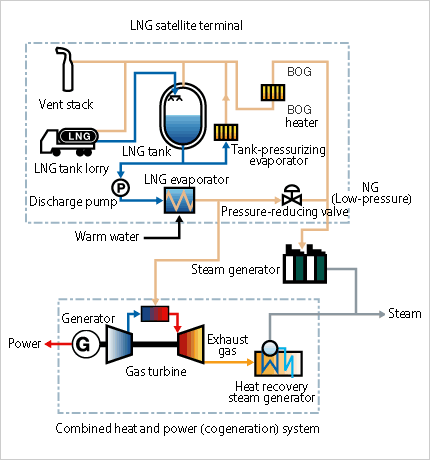
LNG satellite system is constituted of LNG tanks, LNG evaporators and other equipments. LNG tanks have function to store the liquefied natural gas (LNG) transported by LNG lorry which is discharged from the LNG terminal .
And, the LNG evaporators have function to vaporize the LNG convert to gaseous state from liquid state in order to utilize LNG for gas fuel. IHI can offer gas turbine plant system including LNG satellite system equipment as overall energy supply system to correspond to customer needs.

■System Flow Diagram Example of LNG satellite system
GT/GE Combined System
About Gas Turbine / Gas Engine Combined System
Each type of engine has its own characteristics and features originated from its heat cycle and physical mechanism.
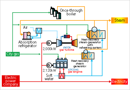
Even if a power plant is constituted of one sort of engines such as only gas turbines, only gas engines or only diesel engines, in most of cases, the power plant could not be optimized to correspond to customer energy demand including electricity and heat(steam & hot water). IHI offers GT/GE combined system which enables to optimize system configuration of power plant constituted of various engines in order to realize optimization of energy saving.
For example, combined with gas turbine used for mainly electricity production and gas engine used for mainly harnessing varible-load, IHI can offer more erergy-efficient power plant system compared with a power plant system constituted of one sort of engines. Even in case that customer facility requires a large amount of steam loads, or in case that the steam loads at customer facility are variable, IHI offers customized gas turbine power plant system installed with HRSG(Heat Recovery Steam Generator) with reheating system or small-scale packase bolier to correspond to variable steam demand of customer facility, can realize high efficient optimized power plant operation by utilizing steam energy for energy saving.
IHI can offer optimized high energy-efficient energy system with Integrated Control System utilized with its own characteristics and features of each engine, because IHI has wide-range full lineup of engines including gas turbines, reciprocating internal combustion engines, diesel engines, and so on.

■System Flow Diagram Example of GT/GE Combined System
Reheating System
About Reheating System
In case a large amount of steam(heat) is generated with BTG (Boiler, Turbine, Generator) power plant system facility, and steam generator converts most of steam from thermal energy to electric energy and surplus steam is utilized at customer facility, if most of thermal energy is utilized at customer facility, IHI can realize high energy-efficient energy power plant system but the electricity efficiency of the gas turbine power plant is not so high.
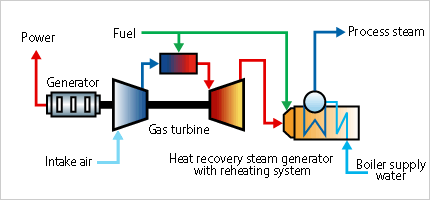
Sometimes the energy consumption schedule or mode of customer energy system changes due to operation condition transformation of customer facility. In case the ratio of electricity energy consumption becomes larger than that of thermal energy consumption, this causes the shortage of electricity power generation, or decrease of the efficiency of energy system. Combined Heat and Power (Cogeneration) system based on Gas Turbine using heat recovery steam generator with reheating system enables to achieve high efficient power generation efficiency while maintaining high levels of overall energy efficiency, and also allows to change the steam(heat) flow rate while maintaining the necessary level of power generation.
IHI offers and proposes customized Combined Heat and Power (Cogeneration) system based on Gas Turbine including the equipments of reheating system.

■System Flow Diagram Example of Reheating System
Cold Thermal Energy Storage System
About Cold Thermal Energy Storage System
Combined Heat and Power (Cogeneration) system is considered to be effective means for energy saving.
However, combined heat and power (cogeneration) system needs to utilize the heat and power simultaneously produced effectively as far as possible.
Steam-injection variable combined heat and power (cogeneration) based on gas turbine is one of the means to fully utilize the heat by converting from thermal energy to electric energy. This CHP(COGEN) system is known as heat utilization method for utilization of excess heat (thermal energy) while generating electric power.
Thermal storage system is known as a time-shift method to save excess heat (thermal energy) for the usage of heat during power shortages.
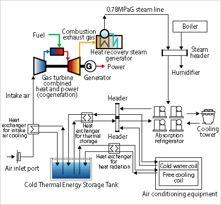
Thermal storage system is constituted of steam accumulator which has function to store heat (thermal energy) as steam, heat (thermal energy) storage tank which has function to store thermal energy as hot water , and cold thermal energy storage tank which has function to store cold thermal energy as cold water and ice. Combination of combined heat and power (cogeneration) and cold thermal energy storage system enable effective thermal energy utilization.
IHI offers and proposes customized energy system including cold thermal storage system facility.

■System Flow Diagram Example of Cold Thermal Energy Storage System


