Development of Co-Firing Technology of Pulverized Coal and Ammonia for Suppressing NOx Generation
ISHII Hiroki, OHNO Emi, KOZAKI Takahiro, ITO Takamasa, FUJIMORI Toshiro
- Reprinted in translation from Transactions of the JSME (in Japanese), Volume 86, Issue 883 -
ISHII Hiroki : R&D Department, Engineering Center, Carbon Solution Business Unit, Resources, Energy & Environment Business Area
OHNO Emi : Associate Director/Deputy General Manager, Carbon Solution Business Unit, Resources, Energy & Environment Business Area
KOZAKI Takahiro : Senior Manager, R&D Department, Engineering Center, Carbon Solution Business Unit, Resources, Energy & Environment Business Area
ITO Takamasa : Doctor of Philosophy, Senior Manager, Energy Conversion Group, Technology Platform Center, Technology & Intelligence Integration
FUJIMORI Toshiro : Doctor of Engineering, Technical Advisor, Technology & Intelligence Integration
In order to reduce CO2 emissions from coal-fired boilers, there are expectations of ammonia, which is free of carbon content, if it is used as fuel. On the other hand, there is a concern that the NOx emissions will increase because ammonia has a higher nitrogen content than coal. In this study, using a 10 MWth test furnace, an ammonia and pulverized coal co-firing test was conducted with ammonia injection velocity as a parameter at 20% co-firing ratio. The result showed that NOx emissions of co-firing are the same as those of single coal combustion. In addition, a co-firing test for evaluating the effect of two-stage combustion ratio, heat input and fuel ratio on NOx was conducted. The results clarified the conditions for reducing NOx emissions in ammonia co-firing.
1. Introduction
Amid a need to reduce CO2 emissions from coal-fired boilers in an effort to prevent global warming, there are expectations of the utilization of hydrogen as a fuel free of carbon content. However, the cost of transportation and storage is one factor i NH i biting the popularization of hydrogen. As a solution, ammonia is attracting much attention as an energy carrier with a high hydrogen content that is relatively easy to liquefy, transport, and store compared to hydrogen. However, since ammonia contains a large amount of nitrogen, there is concern that if it is used as fuel for coal-fired boilers, the amount of NOx in flue gas will increase compared with conventional single coal combustion.
The NOx produced from coal-fired boilers is mainly fuel NOx produced by oxidation of nitrogen contained in coal than thermal NOx generated by oxidation of nitrogen in air. Various measures have been implemented to reduce NOx emissions, such as the two-stage combustion which divides combustion into two stages, whereby fuel-rich combustion is performed in the first stage and NOx generation is suppressed, then complete combustion is performed in the second stage. In two-stage combustion, by performing first-stage combustion at a relatively low air ratio, discharge of the volatile matter within pulverized coal is promoted at the same time as achieving formation of reducing flame, therefore resulting in suppression of NOx generatio. There was concern that it may not be possible to suppress NOx generation using the two-stage combustion method described above when nitrogen-rich ammonia and pulverized coal are co-fired.
In this study, we conducted a pulverized coal/ammonia co-firing test using a combustion test furnace with a heat input of 10 MWth class at a co-firing ratio of 20% (lower heating value (LHV) base) and succeeded in achieving stable combustion while suppressing NOx generation to the same extent as single coal combustion. Moreover, the effect of two-stage combustion ratio on the flue gas characteristics during ammonia co-firing was investigated. Therefore, setting appropriate two-stage combustion ratio enables ammonia co-firing with the same NOx emission level as single coal combustion. This suggests the possibility that ammonia reduces NOx generated in the first-stage combustion region. Furthermore, in order to apply ammonia co-firing technology to actual boiler furnaces, it is necessary to clarify the feasibility of both co-firing under a low-load condition and co-firing various coal types. For this purpose, co-firing tests with different heat input and coal fuel ratio were carried out, and the effect on the flue gas composition was investigated. These tests confirmed that NOx emissions of ammonia co-firing are the same as those of single coal combustion even under a low load condition, which suggests that ammonia co-firing at partial load is possible when applied to commercial furnaces. In addition, as a result of ammonia co-firing under the same combustion conditions using coal with different fuel ratio, it was confirmed that there was no significant difference in the NOx emissions.
2. Test equipment and methods
2.1 Test equipment
The pulverized coal/ammonia co-firing test was performed using a combustion test furnace with a heat input of 10 MWth class. Figure 1 shows the main flow diagram of the combustion test furnace. A burner is positioned on the front of the combustion test furnace. The air supplied from the forced draft fan is heated with the flue gas in the air heater and transported to the burner as combustion air. Part of the combustion air is supplied to the over air port installed at the top of the burner. The air supplied by the mill air fan is also heated with flue gas in the air heater then fed to the pulverizer to be used for drying the coal and transporting the pulverized coal. The pulverized coal is stored in a pulverized coal bin. A predetermined amount of the stored pulverized coal is ejected from the pulverized coal bin with the pulverized coal feeder and fed to the burner with the conveyance air supplied from the primary air fan. The induced draft fan draws in air supplied to the furnace to create negative pressure inside the furnace. The flue gas is sampled at the exit of the test furnace and its composition is measured by a gas analyzer.
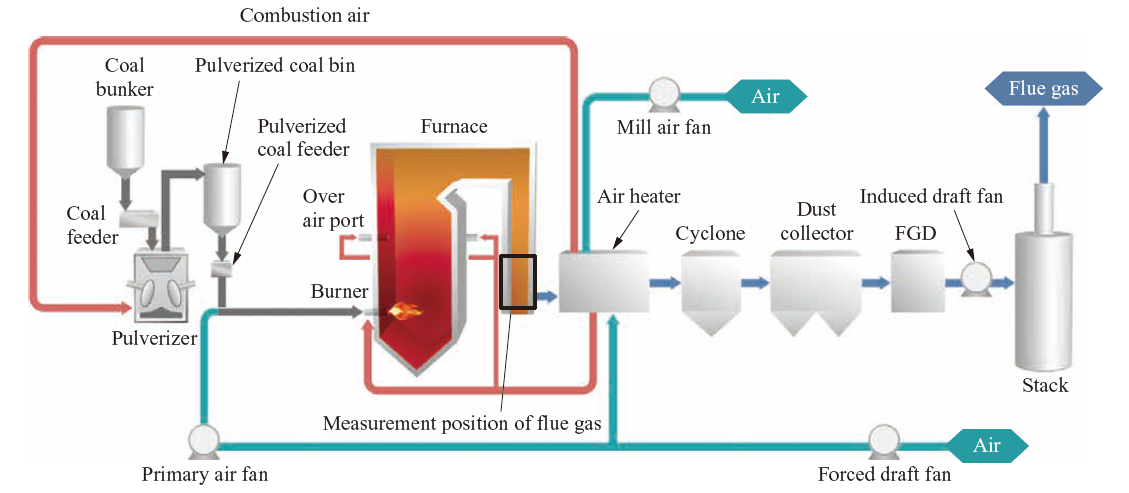
Figure 2 is a schematic of the burner. The burner exit is axisymmetric and the burner has an inner cylinder, outer cylinder, air register, and wind box from the center. Pulverized coal discharged from the pulverized coal bin is supplied with the primary air along the flow path between the inner and outer cylinders. The combustion air is supplied through the outside of the outer cylinder and along a path surrounded by the wind box. The air register positioned in the combustion air flow path has multiple movable vanes in axisymmetric positions, and the combustion air’s swirl force can be adjusted by changing the angles of these vanes. The recirculation flow is established in the front of the burner when the combustion air is swirled. When the high-temperature combustion gas and fuel mix rapidly due to the recirculation flow, discharge of the volatile matter and nitrogen-containing substance within the fuel is promoted, and this achieves both the formation of a stable flame and reduction of NOx in the reducing atmosphere.
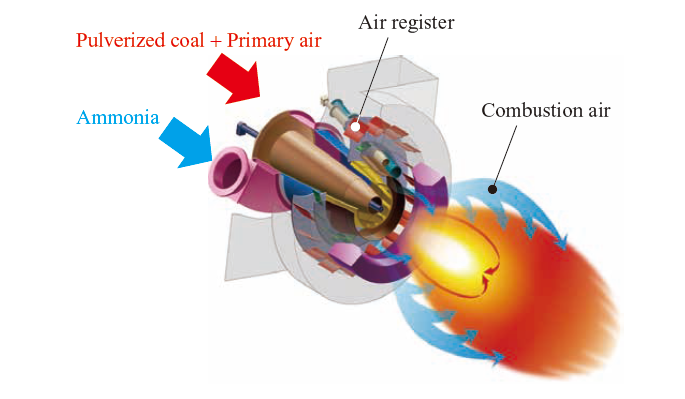
The ammonia supply unit feeds ammonia to the burner and is capable of continuously supplying up to 0.38 ton/h of ammonia. Four cylinders with 0.5 ton capacities can be installed on the ammonia supply unit which is also equipped with two hot water evaporators. Ammonia is vaporized by passing through the evaporators and is transported separately without mixing with air to a special-purpose nozzle installed in the center of the pulverized coal burner while controlling the mass flow rate. When ammonia is supplied, the pulverized coal is combusted in advance and the ammonia is blown in towards the flame.
2.2 Test method
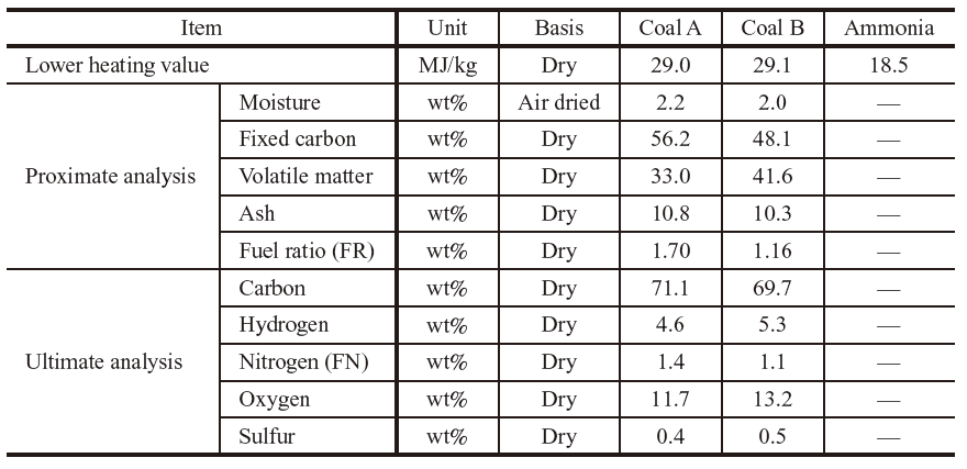
Table 1 shows the properties of the coal and ammonia used in the test. Two types of coal with different fuel ratios were prepared. The heat input of the combustion tests is set to between 7 and 10 MWth. The flow rate of ammonia is adjusted so that the co-firing rate is 20% in this series of tests. In order to evaluate the difference of NOx in flue gas during ammonia co-firing from that during single coal combustion, flue gas is continuously sucked at the test furnace exit and NOx is measured with an analyzer. In addition, flue gas is sucked and sampled with a probe and Cl2O concentration, NH3 concentration and unburnt coal (UBC) in the ash were analyzed.
Table 1 Properties of coal and ammonia
3. Test results and insights
3.1 Effect of ammonia injection velocity on NOx emissions and feasibility of pulverized coal/ammonia co-firing
Figure 3 shows time series data of CO2 and O2 concentration in the flue gas and NH3 concentration at the inlet of the stack for single coal combustion and ammonia co-firing. Ammonia co-firing was performed under the ammonia injection velocity conditions mentioned hereinafter. It was confirmed that at ammonia co-firing, compared to single coal combustion, the amount of coal combustion reduced by 20% and CO2 concentration in the flue gas also reduced by 20%. NH3 concentration was equivalent to that of single coal combustion, and it is considered that the injected ammonia is practically completely burned in the furnace. The small fluctuations in gas composition show stable combustion.
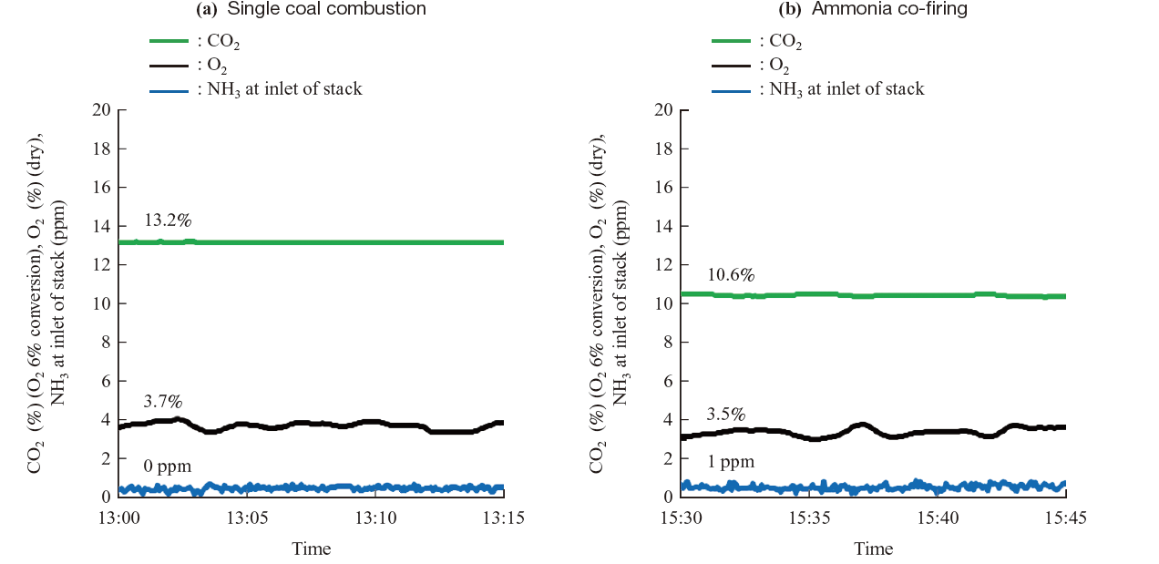
Fig. 3 Time history of flue gas composition. In both cases of single coal combustion and ammonia co-firing, CO2, O2 and NH3 concentration at inlet of stack have small fluctuation in time.
Figure 4 shows the burning flame at single coal combustion and 20% ammonia co-firing. Figure 4-(b) shows the flame created by ammonia co-firing when the swirl force of the combustion air is relatively weak. We confirmed that, in this case, the ignition point of the flame is further from the burner port than that of single coal combustion. This is considered to be due to the ammonia with low burning velocity. Figure 4-(c) shows the flame in ammonia co-firing where the swirl force of the combustion air has been increased and adjusted. At this condition, the ignition point of the flame is similar to that of single coal combustion.
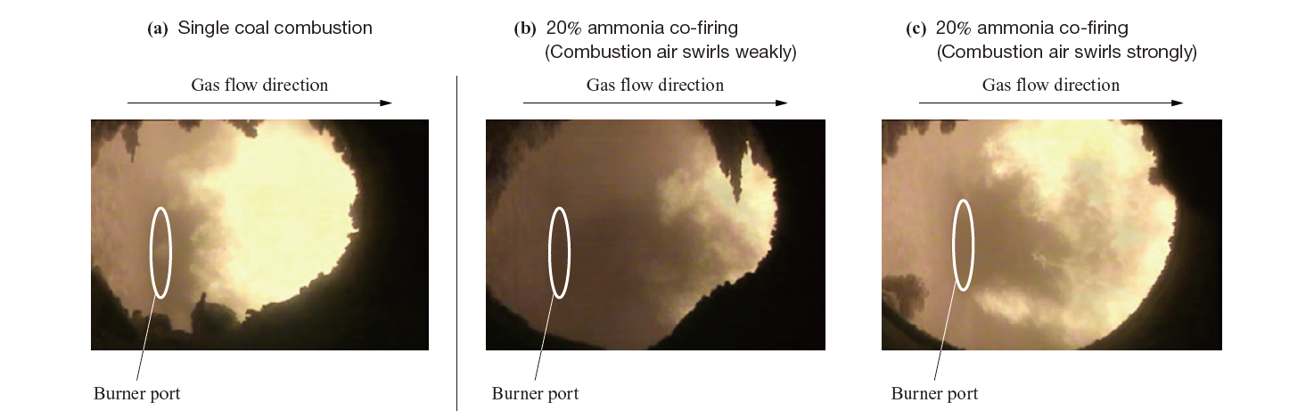
Fig. 4 Flame appearance. In case of ammonia co-firing with weak swirl of combustion air, ignition point is distant from burner port compared with that of single coal combustion. With strong swirl of combustion air, it is the same level as that of single coal combustion
Due to the results of stable flue gas composition over time, absence of unburned ammonia, and formation of a flame similar to that of single coal combustion, we judge ammonia co-firing to be possible using the method of ammonia injection from the center of the pulverized coal burner. The ignition point of the flame is adjusted to the same as that of single coal combustion by the ammonia injection velocity.
Below described is a pulverized coal/ammonia co-firing burner. The pulverized coal/ammonia co-firing burner developed for this study is of a structure whereby ammonia is blown into a recirculating flow area where the flame forms in the front of the burner. This structure aims to suppress oxidation of ammonia by supplying ammonia to a strong reduction zone. To investigate the effect of the ammonia injection velocity from the center of the burner to the furnace on NOx emissions, the test was conducted for two ammonia velocities, a base velocity and a velocity five times the base flow velocity. The base velocity was determined by numerical simulation to have sufficient momentum to ensure the ammonia plunges into the recirculating flow of the pulverized coal flame.
Figure 5 shows the relationship between the ammonia injection velocity, NOx concentration and NO conversion ratio (CR) under the conditions of a heat input of 10 MWth, a two-stage combustion ratio of 30%, an air ratio of approx. 1.2, and an ammonia co-firing ratio of 20%. The ammonia injection velocity used in the Fig. 5 is a normalized, relative value setting the base velocity as 1. CR is defined with formula(1).a
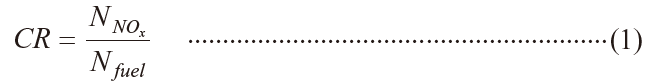
Here, N NOx expresses the nitrogen level in flue gas NOx and N fuel expresses the nitrogen level contained in the injected fuel (coal and ammonia).
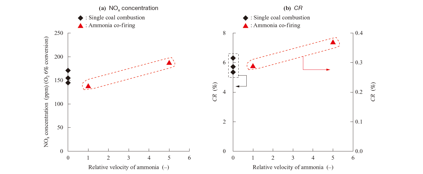
Under the condition of the co-firing with the base ammonia injection velocity, NOx concentration was 144 ppm compared to 154 to 171 ppm at single coal combustion, which was 6 to 16% lower than that at single coal combustion. However, when the ammonia injection velocity five times the base was used, NOx concentration was 187 ppm, which was between 20 and 30 ppm greater than that at single coal combustion. This is considered that because if the ammonia injection velocity is too high, the ammonia will not react in the burner recirculating flow zone and oxidation of the ammonia in the two-stage combustion region leads to an increase of NOx.
The abovementioned result suggests that if the ammonia is supplied from the burner center at the appropriate velocity, NOx can be suppressed to the same level as single coal combustion.
3.2 Effect of two-stage combustion ratio and air ratio on flue gas composition
Two-stage combustion ratio ( R t.s) , which is later defined by Equation(3), is an important parameter for controlling NOx emissions in coal-fired boilers. To investigate whether the adjustment of R t.s enables to control NOx emissions in flue gas during ammonia co-firing, the combustion test with R t.s as a parameter was conducted. Set values in the test are as follows: a heat input of 10 MWth, an air ratio of 1.1 to 1.2, and an ammonia co-firing ratio of 20%.
Figures 6-(a) and -(b) show the relationship between R t.s and NOx concentration in flue gas and the relationship between R t.s and CR, respectively. NOx concentration of single coal combustion decreases monotonically as R t.s increases from 20 to 40%. In contrast, NOx concentration of the ammonia co-firing decreases as R t.s increases between 20 and 30% and increases as R t.s increases over 30%. This is considered to be because UBC, which had remained until the two-stage combustion process, increased and burned with air for two-stage combustion with high R t.s at ammonia co-firing. In the test conditions, the CR was 4 to 10% at single coal combustion and 0.2 to 0.4% at ammonia co-firing. The total amount of nitrogen of the fuel injected into the furnace was approximately 17 times larger at ammonia co-firing than at single coal combustion. NOx concentration is almost the same level, therefore the CR at ammonia co-firing is one-seventeenth compared to single coal combustion.
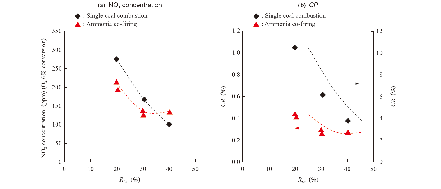
Figure 7 shows the relationship between R t.s and UBC in the ash. The amount of UBC in the ash was the same for both ammonia co-firing and single coal combustion. Therefore, by setting appropriate R t.s, ammonia co-firing with the same NOx emission level as single coal combustion is possible.Then, the effect of first-stage air ratio (λ1) on NO is described below. In this test, air ratio (λ), R t.s, λ1, and second-stage air ratio (λ2) are defined by the following formulas.
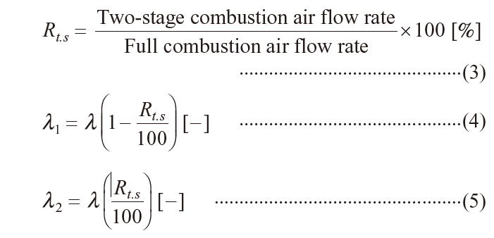
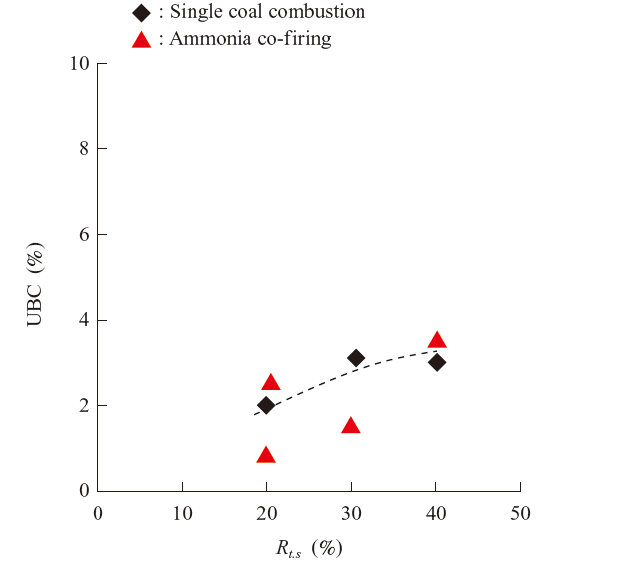
Figure 8 shows the relationship between λ1 and CR when λ2 is between 0.3 and 0.4.
In the case of ammonia co-firing, when λ1 decreases from 0.9 to 0.8, the CR decreases, however this vicinity of 0.8 is the minimum point, and when λ1 decreases further, the CR begins to increase. For single coal combustion, however, CR decreases monotonically as λ1 decreases from 0.9 to 0.75.
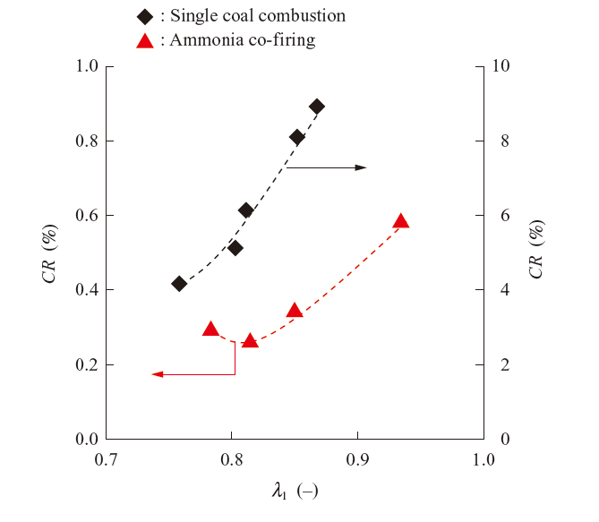
Consideration below is on the result that the distribution of CR in the case of ammonia co-firing has minimum point at approximately 0.8 of λ1 (in contrast to that in single coal combustion within the similar range of λ1). It is reported that NOx emissions in single coal combustion decreases as R t.s increases, however once a certain value is exceeded, it turns to increas(3). This is because, when λ1 is low, NOx generation is suppressed in the first-stage combustion region, however a large amount of UBC remains, therefore NOx is generated in the second-stage combustion region when this UBC undergoes combustion. In other words, there is an optimal λ1 that minimizes the total-amount of NOx generation due to the fuel NOx generation in the first-stage combustion and combustion of UBC in the second-stage combustion. Volatile matter in coal and ammonia, which are both gaseous fuel, combust during first-stage combustion, however in the case of ammonia co-firing, more gaseous fuel is burned compared to single coal combustion. Therefore, it is more likely that UBC increases and the optimal λ1 becomes larger than that at single coal combustion.
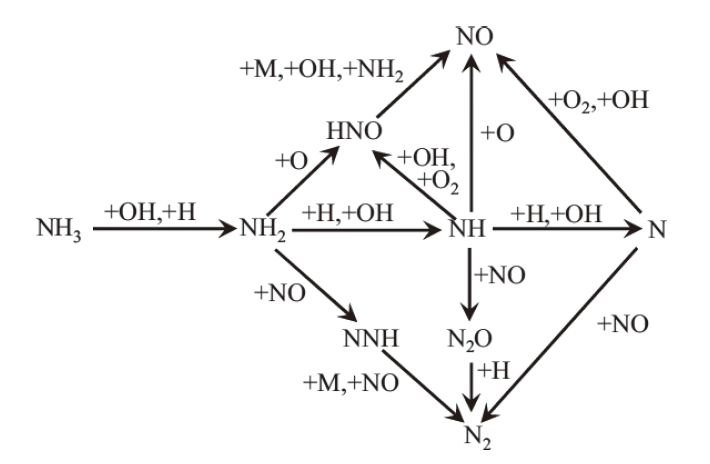
NH3 oxidation pathway in Fig. 9 shows that NH3 generates radicals of NH i (i = 0, 1, 2) due to the oxidation by OH and H, then NH i reacts with O, H, or OH to create NO, and meanwhile Cl2 is generated through a reaction between NO and NH. In the first-stage combustion region where air ratio is relatively low, there is not an abundance of O and OH, therefore an NO reduction reaction caused by NH i is superior. It is presumed to be the reason why, even when co-firing with ammonia high in nitrogen content, NOx generation can be suppressed to the same level as single coal combustion.
Moreover, the increase in CR in relation to λ1 increase is relatively smaller for ammonia co-firing. That means that ammonia co-firing will be much more effective in suppressing NOx generation than single coal combustion in the higher λ1 conditions, or in other words, when the two-stage combustion conditions are low. There is a strong tendency for sulfidation corrosion to occur in a reducing atmosphere, however by applying pulverized coal/ammonia co-firing, the possibility of reducing sulfidation corrosion of the heat transfer tube near the burner while suppressing NOx generation is suggested.
3.3 Effect of heat input on flue gas composition
When applied to actual boilers, it is expected that ammonia co-firing should be applicable at wide load condition. In the low load range, there is concern about combustion stability and emission characteristics of the ammonia co-firing because the temperature in the boiler furnace decreases. In this section, in order to confirm whether the flue gas composition is the same for ammonia co-firing and single coal combustion even in the low load range, pulverized coal and ammonia were co-fired at a low load and the flue gas composition was evaluated. Figures 10-(a) and -(b) show the relationship between heat input and NOx concentration in flue gas and the relationship between heat input and CR, respectively. Figure 11 shows the relationship between heat input and the UBC in the ash. Generally, in boiler furnaces, the λ increases in accordance with the decrease of load to ensure stable combustion. In this test, the situation was simulated by making the λ of 1.2 with a heat input of 8.6 MW, however with a heat input of 7.3 MW and 6 MW, the λ increased to 1.4 and 1.7, respectively.
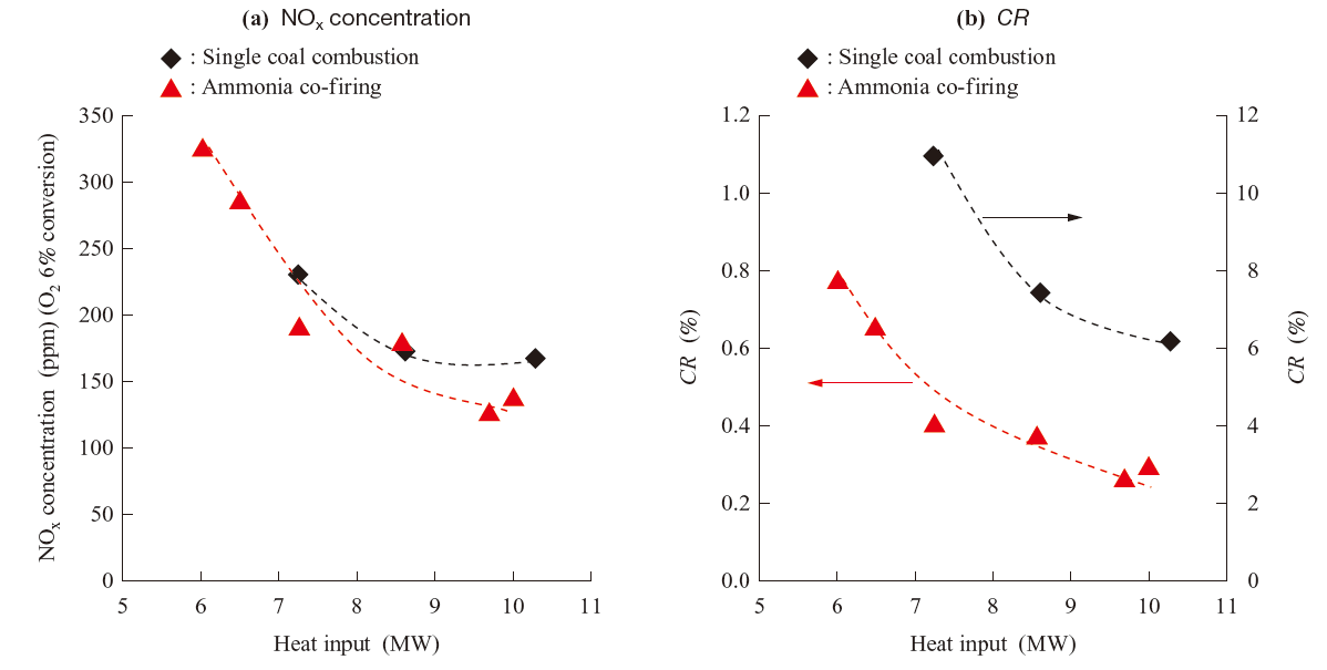
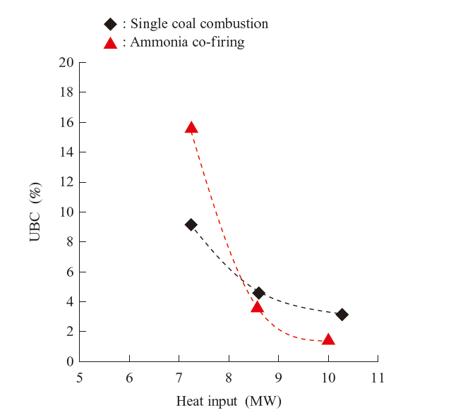
Figure 10-(a) shows that NOx increases as heat input decreases in both single coal combustion and ammonia co-firing, however the increasing trend in ammonia co-firing is almost the same as that in single coal combustion. This suggests that even in the low load range, NOx in ammonia co-firing is almost the same as that in single coal combustion. From Fig. 11, however, it can be seen that with a heat input of 7.3 MW, the amount of UBC in the ash in ammonia co-firing is approximately twice that in single coal combustion. Under the conditions of the lower heat input, the ammonia injection velocity decreases. The penetration of ammonia in the burner is reduced, and the ammonia becomes easier to mix with the combustion air in the vicinity. As a result, the mixing of pulverized coal and combustion air was suppressed, which may cause an increase in the UBC in the ash. If ammonia is injected at the base flow velocity under these conditions, it may be possible to suppress the increase in UBC in the ash.
3.4 Effect of coal fuel ratio and nitrogen content on flue gas composition
In a commercial plant, subbituminous coal, which has a lower fuel ratio, may be used as fuel in addition to bituminous coal. In order to investigate the effect of the coal fuel ratio on the flue gas composition at ammonia co-firing, a combustion test with the coal of the lower fuel ratio was conducted. As shown in Table 1, the test coal had fuel ratios (FR) of 1.16 and 1.70. The heat input condition was fixed to 7 MW.
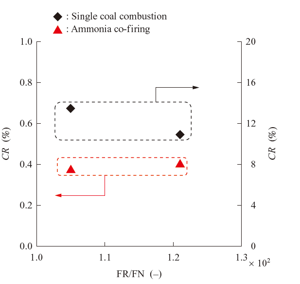
Figure 12 shows the relationship between the ratio of FR and FN (coal nitrogen content shown in Table 1) and CR in the single coal combustion and ammonia co-firing conditions. Within the range of FR/FN in this test, however, CR is considered not to make significant difference as it is 11 to 13%. It was confirmed that the CR increases parallel to increases in FR/F(4). For the ammonia co-firing condition, it was about 0.4 and its change with FR/FN was small. The result shows that the effect of coal FR/FN on NOx emissions at ammonia co-firing is small. This is presumably because 90% or more of the nitrogen contained in the injected fuel (coal and ammonia) comes from ammonia in the case of 20% ammonia co-firing and the absolute amount of the injected nitrogen does not significantly differ within the range in this test. In addition, this result suggests that ammonia does not affect NO generation at the test furnace exit in the case of ammonia co-firing, so that ammonia is considered to be reduced to N2 on the way to the furnace exit even if it oxidizes to NO in the furnace. It is important to note that further data is required to investigate this consideration.
Figures 13-(a) and -(b) show the measurement values at the furnace exit of N2O concentration and NH3 concentration, respectively. Since N2O has a global warming coefficient 298 times greater than CO2, it is not possible to expect a reduction in greenhouse effect when more N2O is discharged at ammonia co-firing even if CO2 is reduced. N2O concentration was measured to understand the value in the case of ammonia co-firing. NH3 concentration was measured to check if ammonia injected as fuel reliably burned.
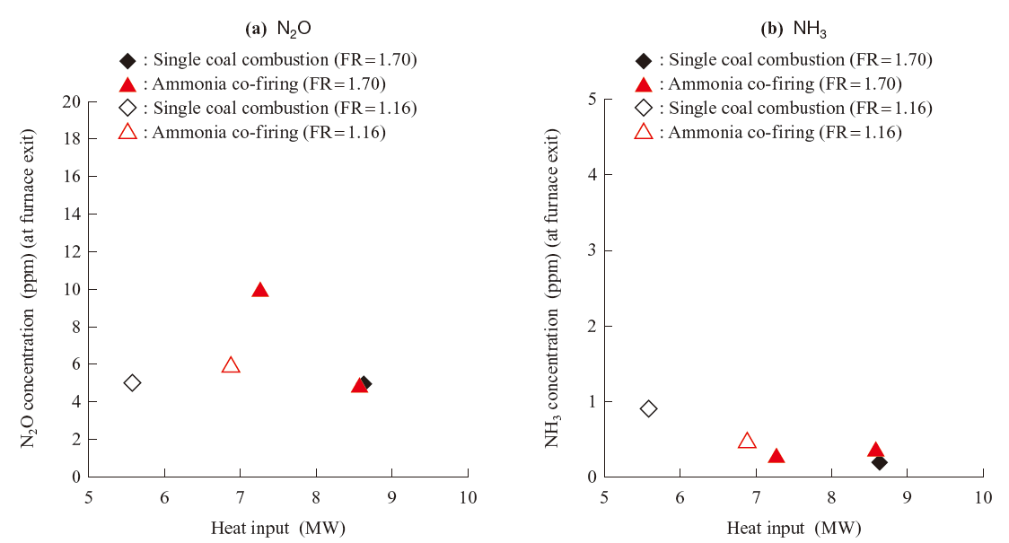
N2O concentration was 5 ppm at single coal combustion in the test conditions. In the case of ammonia co-firing, N2O concentration was 6 to 10 ppm, which is 1 to 5 ppm higher compared to single coal combustion. This is because the furnace internal temperature is lower in ammonia co-firing than in single coal combustion. Flame radiation of ammonia co-firing is lower than that of the single coal combustion due to smaller amount of the coal particle and the lower flame temperature. The value in ammonia co-firing was larger than that in single coal combustion presumably because N2O in single coal combustion is more likely to be generated with lower temperatur. Note that a large coal fired boiler has larger heat input than this test equipment. With the larger heat input, N2O emissions in ammonia co-firing are considered to be the same level as that in single coal combustion because the temperature in furnace is sufficiently high even in ammonia co-firing.
NH3 concentration was 1 ppm at single coal combustion and 0.5 ppm or less in the ammonia co-firing conditions, which is the same level as single coal combustion. Therefore, it is considered that ammonia injected as fuel is almost completely burned in the furnace in the range of the tested coal (FR 1.16 to 1.70).
4. Conclusion
With the ammonia co-firing burner developed in this study, combustion tests were conducted to evaluate the effect of difference in heat input and coal fuel ratio on the flue gas composition at the ammonia co-firing ratio of 20%. The results are as follows:
(1) In ammonia co-firing at rated load, NOx concentration can be controlled at the similar level to that in single coal combustion by appropriately setting the ammonia injection velocity and R t.s. In addition, it was confirmed that NOx concentration had the distribution with the minimum point according to the change of R t.s.
(2) Even with a heat input lower than the rated value, the NOx concentration in ammonia co-firing was the same level as that in single coal combustion.
(3) With a coal fuel ratio and nitrogen content ratio (FR/FN) between 1.1 × 10² and 1.25 × 10², there was no significant difference in the CR in ammonia co-firing, therefore coal volatile matter and nitrogen content have little impact on NO generation. Moreover, NH3 concentrations at the furnace exit were in the same range both in ammonia co-firing and in single coal combustion. Within the range of fuel ratio in this test, ammonia co-firing is suggested to be applicable because ammonia is considered to be almost completely consumed in the furnace.
In the case of low-load ammonia co-firing, the amount of UBC in the ash exceeded that of single coal combustion. This is considered a phenomenon unique to the test furnace with a single burner. We will ascertain the characteristics in the combustion test with a multi-burner furnace in future. Moreover, in order to improve the versatility of ammonia co-firing technology, we will develop ammonia co-firing technologies for higher co-firing ratio.
— Acknowledgments —
This study was entrusted to the researchers under the topic “Energy Carriers - Ammonia Direct Combustion” (administered by the Japan Science and Technology Agency (JST)) within the Cross-ministerial Strategic Innovation Promotion Program (SIP) of the Council for Science, Technology and Innovation, Cabinet Office, Japan. We would like to acknowledge the support of these entities.
REFERENCES
- H. Kobayashi, A. Hayakawa, K. D. K. A. Somarathne and E. C. Okafor : Science and technology of ammonia combustion, Proceedings of the Combustion Institute, Vol. 37, 2019, pp. 109-133
- J. C. Kramlich and W. P. Linak : Nitrous oxide behavior in the atmosphere, and in combustion and industrial systems, Progress in Energy Combustion Science, Vol. 20, 1994, pp. 149-202
- H. Makino and M. Kimoto : Low NOx combustion technology in pulverized coal combustion, Journal of Chemical Engineering of Japan, Vol. 20, No. 6, 1994, pp. 747-757 (in Japanese)
- H. Makino, M. Sato and M. Kimoto : Influence of Coal Properties on Emission Characteristics of NOx and Unburned Carbon in Fly Ash in Pulverized Coal Combustion, Journal of the Japan Institute of Energy, Vol. 73, Iss. 10, 1994, pp. 906-913 (in Japanese)
- H. Makino, M. Kimoto, M. Sato and T. Ninomiya : NOx reduction by multistage air injection on pulverized coal combustion, Journal of the Fuel society of Japan, Vol. 69, No. 9, 1990, pp. 856-862 (in Japanese)