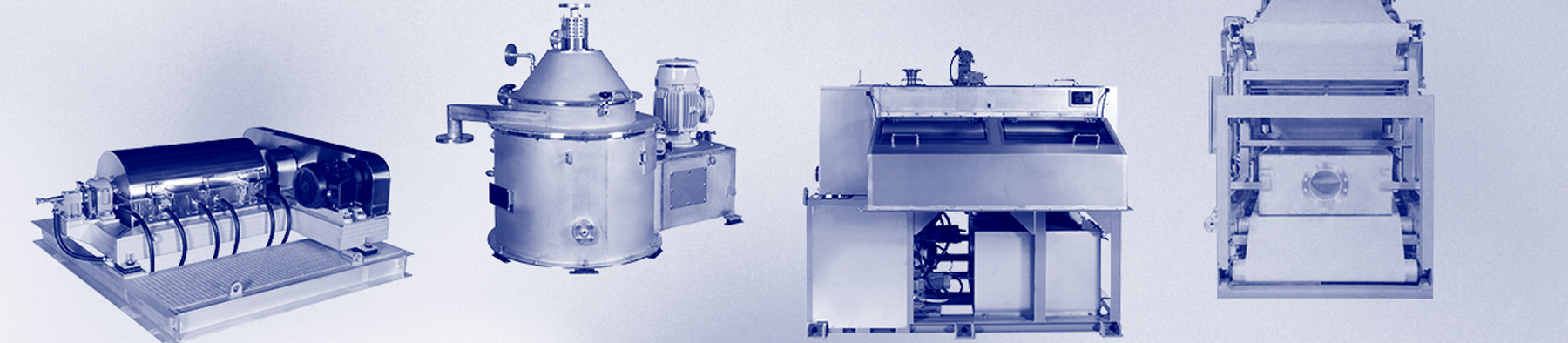
SEPARATOR / DEHYDRATOR
- TOP
- SEPARATOR / DEHYDRATOR
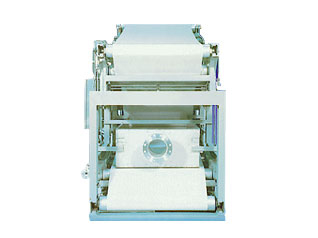
- Belt Press Dehydrator
Belt Press Dehydrator
Suitable not only for sewage and human waste treatment but also in the manufacturing processes
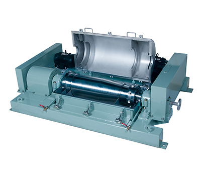
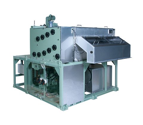
Of all our separators and filters, the Belt Press Dehydrator achieves the lowest water content rate of cake. The NI-M series was developed by appropriately combining the low-pressure and high-pressure dehydration sections to achieve outstanding dehydration while requiring minimal installation area. This belt press model has exceptional features not found in other belt presses and is available in various sizes to handle different processing capacities.
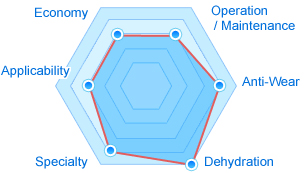
- Economy
- 3
- Adaptability
- 3
- Specialty
- 4
- Dehydration capability
- 5
- AntiーWear
- 4
- Operation / Maintenance
- 3
- Total
- 22
 About the evaluation criteria
Features
- High-pressure dehydration
- Optimal press roller arrangement
- Outstanding dehydration efficiency
- Large Diameter Pressure Roller
- Perforated roller
Flow
The main body of the belt press is equipped with the valve unit panel, flocculator, and oil pump unit as standard features. Moreover, control panels, washing water pumps, strainers, and compressors, among others, are available as optional peripheral equipment.

Operating Principle
Belt Press Dehydrator System Diagram

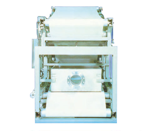
Five Key Features to Further Enhance Dehydration Efficiency
- 1High Pressure Dehydration
- Results in low water content rate of cake The dehydration mechanism comprises hydraulic cylinders and specialized high-pressure belts. Compared to traditional dehydrators, this system enables cake yields with a 5 to 10% reduction in the water content rate. Moreover, the high-pressure belts are long, narrow strips arranged side by side, distributing the pressure evenly for effective filtrate disposal.
- 2Large Diameter Pressure Roller
- Smooth and gradual pressure control The first stage of the pressurized dehydration rolling process involves a large-diameter roller. The roller diameter becomes smaller as the filter cloth advances to ensure optimal increase of pressure. This method achieves an effortless and reliable dehydration throughout the entire process from the gravity filtration section to the low-pressure and high-pressure filtration sections. As a result, even sludge that had previously been difficult to dewater can be processed effectively.
- 3Optimal press roller arrangement
- Compact and structured design The filter cloth advances from the bottom upward, preventing the filtrate from flowing into the subsequent dehydration roller. This ensures that the filtrate can be collected from each roller without fail. Moreover, the rollers are efficiently arranged in a tiered structure to minimize the number of rollers necessary. The installation area required is extremely compact in comparison to its dehydration surface area.
- 4Perforated roller
- Four times the dehydration capacity of single-sided dehydration By perforating the surface of the main dehydration roller, the filtrate can be removed from both surfaces of the filter cloth, resulting in a dehydration capability that is four times that of the single-sided dehydration system. The perforations also prevent cake blockage to ensure stabilized performance.
- 5Outstanding dehydration efficiency
- Significant increase in dehydration capability The filtration and dehydration performance is extremely high in the gravity and low-pressure filtration sections leading up to the high-pressure filtration section, resulting in cakes with exceptional consistency. This enables the high-pressure dehydration section to function effectively, allowing a wider range of applications to various types of sludge.
Dimensional specifications


Specifications
| Filter cloth | Outward Size | |||||
|---|---|---|---|---|---|---|
| Filter cloth effective width m |
Filter cloth width m |
Filter cloth speed m/min |
Width (W) mm |
Length (L) mm |
Height (H) mm |
|
| NI-M50 | 0.5 | 0.6 | 0.5−5.0 | 1200 | 3100 | 1920 |
| NI-M100 | 1.0 | 1.1 | 0.5−5.0 | 1700 | 3100 | 1920 |
| NI-M150 | 1.5 | 1.6 | 0.5−5.0 | 2270 | 4470 | 2470 |
| NI-M200 | 2.0 | 2.1 | 0.5−5.0 | 2770 | 4470 | 2470 |
| NI-M250 | 2.5 | 2.6 | 0.5−5.0 | 3300 | 4540 | 2970 |
| NI-M300 | 3.0 | 3.1 | 0.5−5.0 | 3800 | 4540 | 2970 |
| Output | Washing water | |||||
|---|---|---|---|---|---|---|
| Drive unit kW |
Hydraulic device kW |
Flocculator kW |
Feed mixer kW |
Usage amount L/min |
Pressure MPa(Pe) |
|
| NI-M50 | 0.75 | 0.75 | 0.4 | - | 70 | 0.5 |
| NI-M100 | 1.5 | 1.5 | 0.4 | - | 120 | 0.5 |
| NI-M150 | 1.5 | 1.5 | 0.4 | - | 175 | 0.5 |
| NI-M200 | 1.5 | 1.5 | 0.4 | - | 225 | 0.5 |
| NI-M250 | 2.2 | 1.5 | 0.4 | 0.2 | 275 | 0.5 |
| NI-M300 | 2.2 | 1.5 | 0.4 | 0.2 | 325 | 0.5 |
| Compressed air | Weight、load | |||
|---|---|---|---|---|
| Usage amount L/min |
Pressure MPa(Pe) |
Product Weight ton |
Operation load kN |
|
| NI-M50 | 60 | 0.7 | 2 | 25 |
| NI-M100 | 60 | 0.7 | 3.5 | 39 |
| NI-M150 | 120 | 0.7 | 7 | 79 |
| NI-M200 | 120 | 0.7 | 9 | 98 |
| NI-M250 | 120 | 0.7 | 14 | 152 |
| NI-M300 | 120 | 0.7 | 17 | 182 |
| Connection | Standard Disposal (Treatment) Volume m3/h |
||||
|---|---|---|---|---|---|
| Sludge Inlet A |
Washing water inlet B |
Compressed air inlet C |
Hydraulic Connection D |
||
| NI-M50 | 65A | 25A | Rc1/4 | Rc1/4 | 1.5−2.5 |
| NI-M100 | 65A | 25A | Rc1/4 | Rc1/4 | 3.5−4.5 |
| NI-M150 | 100A | 40A | Rc1/4 | Rc1/4 | 7−9 |
| NI-M200 | 100A | 40A | Rc1/4 | Rc1/4 | 9−11 |
| NI-M250 | 150A | 65A | Rc1/4 | Rc1/4 | 11−14 |
| NI-M300 | 150A | 65A | Rc1/4 | Rc1/4 | 13−17 |
- Note 1: Standard treatment volume is based on the assumption of treating human waste mixed sludge (SS concentration of 2%) and dewatering it (to 80 - 82% water content rate of cake) using the standard nitrogen removal method. The treatment volume may vary depending on the type of slurry, its SS concentration, flocculation method, and desired water content rate of cake. Please inquire with IHI on the dewatering capacities and selection processes regarding the models.