
Case Studies of MBSE Applications in the Aircraft Engine
SAKAI Toshiya, MUROOKA Takeshi, HIROTA Kentaro
SAKAI Toshiya : Manager, Control Systems Engineering Department, Research & Engineering Division, Aero Engine, Space & Defense Business Area
MUROOKA Takeshi : Manager, Advanced Technology Department, Research & Engineering Division, Aero Engine, Space & Defense Business Area
HIROTA Kentaro : Manager, Advanced Technology Department, Research & Engineering Division, Aero Engine, Space & Defense Business Area
In recent years, the functional requirements for aircraft systems have been increasing due to advancements in electronic technology, leading to greater system complexity. As a result, impact assessments during design changes and certification tests have become more complicated, causing longer development periods. Furthermore, the demand for environmental sustainability has intensified, making the integration of diverse technologies, such as electrification and hydrogen combustion, essential. To address these challenges, IHI is utilizing model-based systems engineering (MBSE) to centralize the management of design information and is developing a design process that streamlines impact assessments across multiple components through collaboration with model-based design (MBD).
1. Introduction
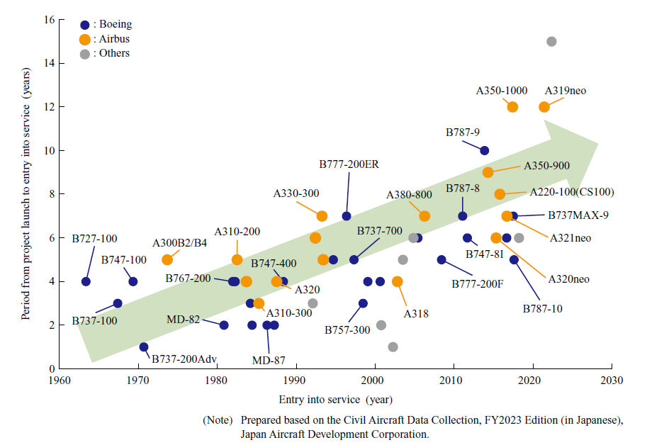
In recent years, the functional requirements for aircraft systems have been increasing due to the remarkable advancements in electronic technology. Consequently, the number of parts that make up aircraft systems and their complexity are increasing every year. They contain approximately three million parts, about 100 times more than automobiles. As a result, the increasing number of design and manufacturing rework due to design changes as well as the growing complexity of certification testing have prolonged development times. This is becoming a significant issue for the aircraft industry. Figure 1 shows the time required to obtain type certification for a civil aircraft.
In the field of aircraft engines, electronic technology has become increasingly reliable, and there is currently a shift from hydraulic and mechanical controls to electronic controls. Electronic controls promise higher performance, improved maintainability, and improved cost-effectiveness. This situation inevitably leads to increased system complexity. In the conventional engine development process, design changes required in the later stages of development made it difficult to evaluate interactions between complex elements, posing challenges that affected the schedule.
Furthermore, there is a growing demand to reduce the environmental impact of aircraft, such as by reducing their CO₂ emissions, in order to make them environmentally friendly. As a result, integration with different technological fields, including electrification, electric hybrid propulsion, and hydrogen combustion technology, will become essential, and engine systems aimed at carbon neutrality are expected to become increasingly complex. At the same time, there is also a growing demand to shorten development times, requiring more efficient development within limited time frames and resources. For these reasons, model-based systems engineering (MBSE) is being increasingly applied across various industries and is also gaining attention in aircraft engine development.
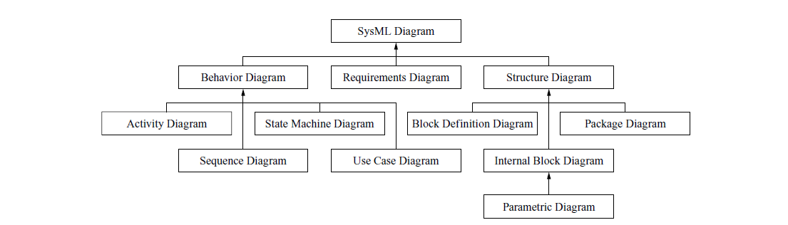
Traditionally, required specifications, design results, development plans, test results, and other information were primarily documented and managed in text- or table-based documents. However, as systems become more complex, the amount of required documentation has exploded, making it increasingly difficult to manage changes and maintain traceability. Furthermore, relying solely on documentation makes it difficult to intuitively understand the overall system structure and behavior, increasing the risk of misunderstandings among stakeholders. MBSE addresses these challenges by shifting from a document-centric approach to a model-centric approach, making the development of complex systems more efficient and effective. MBSE models are descriptive models that visually and systematically represent system structures, behaviors, functions, and interrelationships. Unlike simple diagrams or illustrations, models must be created based on strict rules and formats to support system design, analysis, and management. The modeling language Systems Modeling Language (SysML) is widely adopted as the de facto standard. SysML defines description rules for the diagram classifications shown in Fig. 2.
This paper describes the construction of an MBSE model for aircraft engine systems aimed at shortening development times, which has been undertaken as part of the “Development and Demonstration of Advanced Development and Manufacturing Process Technologies Using Digital Technologies for Aircraft Design, Manufacturing, and Certification/Innovation and Process Integration of Aircraft Design, Certification, and Production Processes”(2) of the Key and Advanced Technology R&D through Cross Community Collaboration Program (K Program) since FY2023. This paper also discusses the design methodology of the model combined with model-based design (MBD), which has also been applied in conventional designs(3).
2. Applying MBSE to aircraft engines
2.1 System design challenges and goals
In preparation for applying MBSE, we reviewed the problems and challenges faced in existing aircraft engine development and design. We believe that MBSE technology is extremely useful in overcoming the technical or departmental barriers that have traditionally tended to be fragmented, enabling efficient collaboration. Therefore, we collaborated not only with system designers but also with experts in various fields, such as aerodynamic design, performance design, structural design, and control design, to comprehensively and multifacetedly organize the challenges we currently face.
- (1)Development and design of similar products
- Aircraft jet engines have seen performance improvements through technological innovation, but their operating principles and structure have remained largely unchanged, with designs primarily extending existing technologies. Therefore, the higher-level requirements could not be analyzed sufficiently, and there was a high possibility that individual technologies would be incompatible when integrated into a system, resulting in significant rework.
- (2)Increasing system complexity
- Engine systems are evolving toward electronic control, rapidly increasing the scale and complexity of these systems. Furthermore, integrating technologies from different fields is necessary in order to reduce environmental impact. This has made the design and verification processes more difficult, creating an urgent need to establish efficient development methodologies.
- (3)Long development cycles
- Aircraft engines take about 10 years from initial development to mass production and are used for 10 to 20 years after mass production begins. This long development cycle makes it difficult to quickly improve processes by implementing the PDCA (Plan-Do-Check-Act) cycle.
- (4)Increasingly complex document management
- In traditional document-based development processes, required specifications, design results, and test results were intricately interrelated, making centralized information management and ensuring traceability cumbersome and labor-intensive.
To address these issues, we are transitioning to a design process that uses systems engineering (SE) techniques to translate challenges into requirements, functions, and technologies. We are also working to establish a system that can quickly respond to new architecture designs by utilizing models to create a system for handling requirements, functions, and design in a digital environment. Through these efforts, we aim to solve social issues, including achieving carbon neutrality, and to develop engines that will contribute to the future of the aviation industry.
2.2 Needs analysis and requirements review
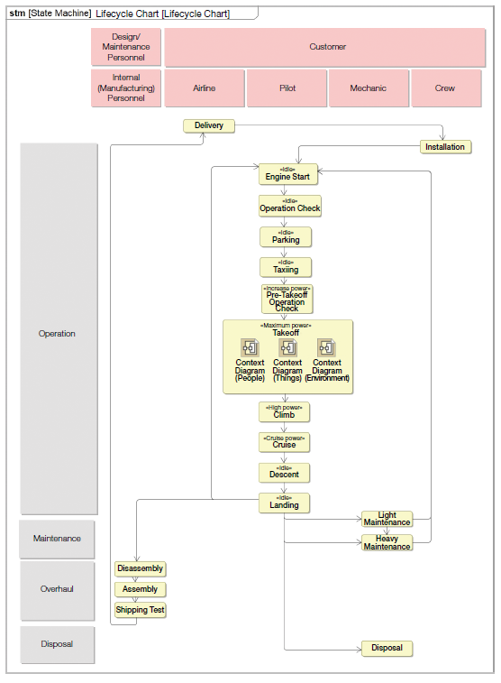
A lifecycle analysis was conducted to understand the entire lifecycle (from development to disposal) required for aircraft engine systems and to clarify the relevant stakeholders. In lifecycle analysis, it is important to understand the overall picture of the lifecycle in terms of time, space, and purpose. Therefore, analysis was conducted using the following procedure. An example of the examined lifecycle diagram is shown in Fig. 3.
- (1)Extract lifecycle stages in chronological order
- To understand the overall lifecycle, we have roughly defined it to include phases other than the user operational phase, such as development, manufacturing, and sales.
- (2)Consideration of stakeholders at each lifecycle stage
- We considered the people and organizations that should be taken into account when formulating requirements for the target development system.
- (3)Categorize scenes for each stakeholder
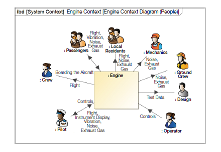
- A context analysis is conducted following the lifecycle analysis. The analysis was conducted to clarify the scope of responsibility for the target system and its boundaries with the external environment, and to extract stakeholder needs and requirements. Since the interface with stakeholders and the surrounding environment differs for each of these contextual scenes, it is necessary to consider each scene to extract all requirements from the relationship among the system, the stakeholders, and the surrounding environment. Figure 4 shows an example of a context diagram for a takeoff scene.
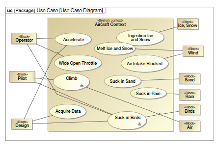
A context analysis was conducted to clarify the boundaries of the target system and identify the stakeholders that will affect the system. Next, a use case analysis was conducted to organize the system’s behavior and purpose in each context and clarify how stakeholders will be involved in the system. By considering the roles of stakeholders, the purpose of use, and specific scenarios, we were able to organize the objectives and functions to be achieved that will form the basis of the system design. An example of a use case diagram created for this analysis is shown in Fig. 5.
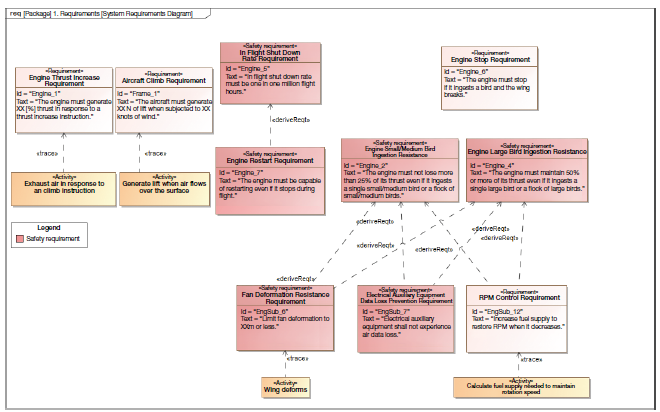
Based on the created use case diagram, stakeholder needs, airworthiness inspection requirements, and other relevant factors, we examined the requirements for the aircraft engine system and created a requirements diagram to clarify the relationships between the requirements. Figure 6 shows an example of the created engine system requirements diagram.
2.3 Functional design
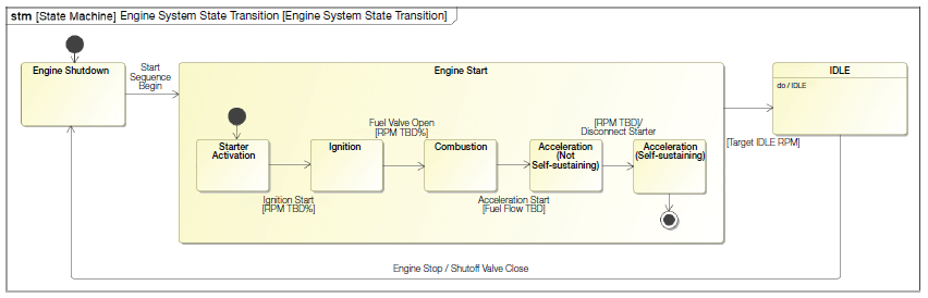
After organizing the requirements for the aircraft engine system, we clarified the behavior of the entire system and designed the functions necessary to achieve the system requirements. State machine diagrams were used to examine the behavior of a single object, while activity diagrams were used to investigate the interaction and behavior of multiple elements as a system. Figure 7 shows an example of a state machine diagram created for engine startup.
Activity diagrams focus on functions and their inputs and outputs, representing behaviors such as execution order, branching, and parallel actions. They define the functionality that the target system needs to meet requirements. In this paper, we examined behavior regarding the following three inputs and outputs:
- Conversion of energy input and output
- Conversion of object input and output
- Conversion of information input and output
Figure 8 shows an example of an activity diagram for engine startup.
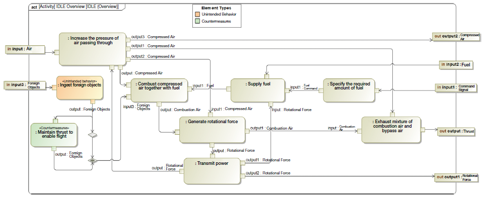
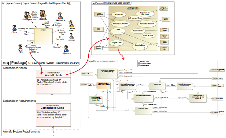
Figure 9 shows the relationships among the analytical results examined so far. Based on the stakeholder relationships organized by context, we identified each stakeholder’s needs and built specific use cases accordingly. Furthermore, we examined the necessary activities for each use case in detail and organized the specific behaviors and functional requirements for the realization of the system. To manage this series of review processes efficiently and reliably, we centralized information using MBSE methodologies. This clarified the relationships among needs, use cases, and activities, ensuring high-precision traceability of various types of information throughout the design and development processes.
2.4 System configuration studies
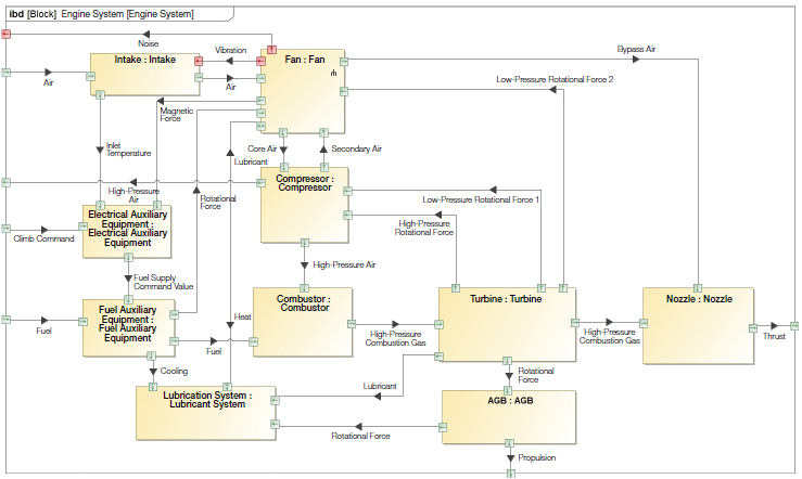
After completing the functional design of the aircraft engine system, we proceeded to examine the physical means for realizing its functions. In the study of the system configuration, we used block definition diagrams, internal block diagrams, and activity diagrams to examine physical elements and allocate them to functions, ensuring that there were no omissions in requirements, functions, or physical elements. Figure 10 shows the internal block diagram of the engine system.
2.5 Benefits of MBSE Modeling
Based on the methodology described in Sections 2.2 to 2.4, we constructed an MBSE model for an aircraft engine system. We believe that using this model provides the following advantages compared to a document-based design process:
- (1)Promoting efficient discussions through integrated design information management
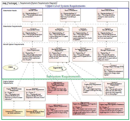
- By consolidating and storing design information within the MBSE model, design information for the entire system is centrally managed. This enables a visual and systematic overview of all system design information, allowing all stakeholders to quickly and easily access the necessary information. Through this integrated information management, all stakeholders can share a comprehensive overview of design content and requirements while fostering constructive and effective discussions. Figure 11 shows an example of a requirements diagram illustrating relationships with upper-level systems.
- (2)Design optimization through visualization of system-wide scope of impact and functional relationships
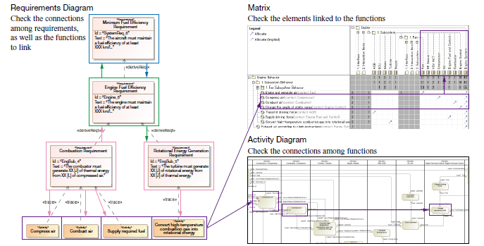
- When requirements or design changes occur, the scope of their impact can be visualized through the MBSE model, enabling quick and accurate assessment of how changes affect other elements and functions. For example, changes to specific requirements can be visualized within the model to show how they affect related subsystems and other functions, making it possible to assess the overall impact. Furthermore, since the relationships among system-wide functions are clarified within the model, we believe that it is possible to detect potential functional conflicts or inconsistencies due to changes in advance and make adjustments, thereby improving the accuracy of the design. Figure 12 shows an example of impact verification using the model.
3. MBSE-MBD linkage
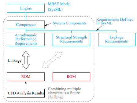
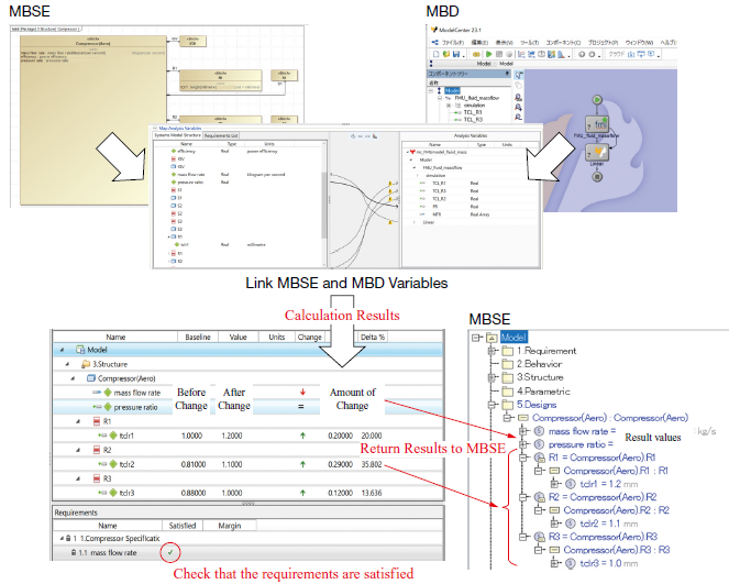
MBSE models are highly useful as a framework for conducting comprehensive evaluations while considering system design requirements and airworthiness inspection requirements. However, performing quantitative evaluations is difficult. To overcome these evaluation limitations, we believe that MBSE-MBD linkage, which combines MBSE model with the computer aided engineering (CAE) analysis technology used in MBD, is essential. As a preliminary step in this trial, we utilized a reduced order model (ROM) derived from a single CAE analysis. This enabled integration with a simplified MBSE model while reducing analysis time. This trial represents a crucial step toward establishing the foundation for MBSE-MBD linkage technology, suggesting potential for improving the efficiency and accuracy of future design processes. Figure 13 shows an image of the linkage, and Fig. 14 shows the results of the linkage trial.
4. Conclusion
This paper introduced a case where MBSE was applied by IHI with the aim of improving the efficiency of aircraft engine system design. By consolidating and centrally managing design information within the MBSE model, design information for the entire system can be shared visually and systematically, allowing stakeholders to quickly access the information they need. This enables efficient and constructive discussions while sharing an overall picture of the design details and requirements. Furthermore, by visualizing the scope of impact using the MBSE model when requirements or design changes occur, it has become possible to quickly and accurately evaluate the impact of changes on other elements and functions. This has clarified the relationships among system-wide functions, creating an environment where design optimization can be achieved by proactively identifying and resolving functional conflicts and inconsistencies caused by changes.
In addition, to improve design accuracy, we investigated MBSE-MBD integration technology combining MBSE model with various CAE analysis techniques and introduced a mechanism for early quantitative evaluation and feeding the results back into the design process. Currently, we are conducting fundamental verification using MBSE and MBD targeting single elements, but we aim to establish technologies for linking multiple elements in the future. This technology will create a system in which multiple designers can evaluate the mutual impacts of their work as the design progresses, with the aim of improving design quality and shortening development time.
- — Acknowledgments —
- Part of the results presented in this paper were obtained as a result of work commissioned (JPNP22007) by the New Energy and Industrial Technology Development Organization (NEDO).
REFERENCES
(1) Japan Aircraft Development Corporation : Civil Aircraft Data Collection, FY2023 Edition, 2024 (in Japanese)
(2) New Energy and Industrial Technology Development Organization : Research and Development Initiative for “Development and Demonstration of Advanced Development and Manufacturing Process Technologies Using Digital Technologies for Aircraft Design, Manufacturing, and Certification”, < https://www8.cao.go.jp/cstp/anzen_anshin/20221227_meti_2.pdf >, accessed 2025-03-02 (in Japanese)
(3) T. Sakai, T. Murooka, K. Hirota, N. Tani, T. Enoki, Y. Kirimura, T. Nambu and K. Kubota : Development of MBSE Application Technology for Aircraft Engines, 62nd Aircraft Symposium, 3C06, 2024 (in Japanese)