Development of Electric Turbocharger for Fuel Cell Systems to Contribute to the Realization of Carbon Neutrality
HAYASHI Katsunori, KANEDA Shinichi, IKEYA Nobuyuki, DAITO Yuichi, KITAMURA Kazuhiro
HAYASHI Katsunori : E-Product Development Project Department, Engineering Center, Vehicular Turbocharger Business Unit, Industrial Systems and General-purpose Machinery Integration
KANEDA Shinichi:Manager, E-Product Development Project Department, Engineering Center, Vehicular Turbocharger Business Unit, Industrial Systems and General-purpose Machinery Integration
IKEYA Nobuyuki : Chief Engineer, Vehicular Turbocharger Business Unit, Industrial Systems and General-purpose Machinery Integration
DAITO Yuichi : Manager, E-Product Development Project Department, Engineering Center, Vehicular Turbocharger Business Unit, Industrial Systems and General-purpose Machinery Integration
KITAMURA Kazuhiro : Manager, E-Product Development Project Department, Engineering Center, Vehicular Turbocharger Business Unit, Industrial Systems and General-purpose Machinery Integration
Fuel cell systems such as the fuel cell vehicle (FCV) are being used more and more toward the realization of carbon neutrality. IHI is developing a new electric turbocharger (ETC) that has high efficiency to meet the requirements in regards to performance, cost, and reliability of various fuel cell systems. In addition to meeting the needs from the improvement in efficiency of the systems, we are also working to improve manufacturability with a view to future mass production. This paper introduces the strengths of IHI’s newly developed ETC-M, the benefits that the ETC-M brings to fuel cell systems, and the elemental technologies that support them.
1. Environment surrounding fuel cell systems
The utilization of hydrogen is expected to be an option to realize carbon neutrality. For example, the EU announced its hydrogen strategy in 2020, which aims to produce 10 million tons of renewable hydrogen by 2030(1). Many countries are supporting and subsidizing the utilization of hydrogen. The German government announced that it would provide support for heavy-duty fuel cell trucks, and the Chinese government announced in 2020 that it would subsidize the development of supply chains in the fuel cell vehicle (FCV) industry(2). With such efforts, the FCV industry is expanding.
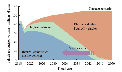
Figure 1 shows the forecast scenario of vehicle production for 2050(3). The percentages of internal combustion engine vehicles and hybrid vehicles are expected to fall rapidly after 2030, and be replaced by electric vehicles (EV) and FCVs. According to the Japan Automobile Manufacturers Association (JAMA), EVs are expected to become mainstream in the segment of compact passenger vehicles, and FCVs in the segment of heavy-duty commercial vehicles(4). Since hydrogen has higher energy density than batteries, FCV is a suitable option for heavy-duty commercial vehicles, which require high power and are driven long distances.
IHI began its research on compressors for fuel cell systems in 2002, and its compressors have been mounted in stationary fuel cell systems (systems for supplying power to facilities) and FCVs. In 2018, IHI mass-produced the world’s first (according to our research) turbine-equipped Electric turbocharger (ETC) for Daimler AG (Germany) vehicles.
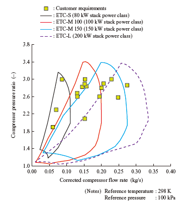
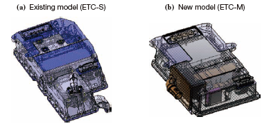
This ETC covers the low power stack region indicated as ETC-S in Fig. 2. With the expanded application of fuel cells to heavy-duty commercial vehicles, the power of fuel cell systems is getting high. Therefore, IHI is expanding its lineup of ETCs for the M, L, and LL power classes to meet customer demand. IHI has newly the ETC-M that covers the M power class The ETC-M has been improved in efficiency and manufacturability relative to the existing model ETC-S. The production volume of ETCs for fuel cell systems is expected to grow in the future, and therefore, we are required to shift from small production to mass production. This paper introduces the new model ETC-M, which is intended to be a highly efficient product that can be used in a wide range of applications, including not only passenger vehicles but also commercial vehicles, boats and ships, railways, and stationary fuel cells, and has a structure that allows mass production.
2. Fuel cell systems and ETC
2.1 Fuel cell systems
Fuel cell systems consist mainly of a hydrogen tank, fuel cell stack (FC stack), power management system, and electric compressor. Fuel cell systems generate direct current with hydrogen and atmospheric oxygen. Oxygen is supplied by compressing air with the electric compressor.
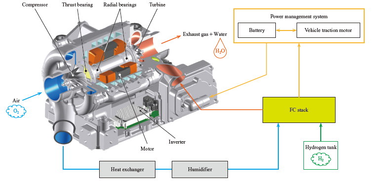
Figure 3 shows the system flow of a fuel cell system in operation. In this system flow, the ETC is used as an electric compressor. The ETC consists of a compressor, turbine, motor, bearing, and inverter. The air (oxygen) compressed by the ETC and the hydrogen supplied from the hydrogen tank react chemically in the FC stack to generate electricity and charge the battery. The charged electricity is used to drive the traction motor and ETC. After the chemical reaction takes place in the FC stack, exhaust gas (moist air) and water are discharged from the FC stack. They pass through the turbine to the outside. At this time, the turbine recovers energy from the exhaust gas and uses it to assist the rotation of the ETC. The compressor and turbine are arranged on the same shaft to form a rotating body (rotor). The rotor is supported by air bearings. The inverter supplies power to the motor and has an interface to communicate with the vehicle systems.
2.2 Strengths of IHI’s ETC
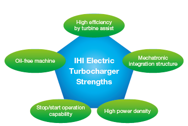
IHI has been delivering many kinds of rotating machinery, including aircraft engines and turbochargers, for many years. IHI has been developing ETC with these existing technologies, and has successfully equipped its ETC with the following five strengths (Fig. 4) .
- (1) High efficiency by turbine assist
- - The energy of the exhaust gas discharged from the FC stack is recovered by the turbine and is used to cover 30% of the compressor power. This enables downsizing of the ETC and reduction of power consumption.
- The reduced power consumption of the ETC provides higher efficiency of the fuel cell system, thereby making it possible to render the system smaller and more powerful according to the intended use. - (2) Oil-free machine
- To prevent the performance of the fuel cell from deteriorating, an oil-free structure has been realized by adopting air bearings.
- (3) Stop/start operation capability
- Applying coating on the air bearings has enabled stop/start operation that follows the fuel cell system. This saves electric power when the fuel cell system is not in use.
- (4) High power density
- The rotational speed has been increased, thereby increasing the power density by 58% from an existing production model.
- (5) Mechatronic integration structure
- The turbocharger including the motor and the inverter were further integrated, optimizing the overall size to achieve downsizing. This enabled downsizing of the entire fuel cell system.
3. Comparison of electric compressor systems
3.1 Comparison of electric compressor systems with and without a turbine
At rated operation, moist air at 80 to 100°C is discharged from the FC stack as an exhaust gas. The power required to turn the compressor can be supplemented by recovering the energy contained in the exhaust gas with the turbine. Figure 5 shows the relationship between the compressor pressure ratio and compressor power in a ratio range of 1.5 to 3.2. Also, the amount of power recoverable with a turbine is superimposed on the same graph. The amount of turbine power recoverable depends on the pressure loss in the FC stack and the pressure difference that can be used by the turbine. From the graph, it can be seen that as the parameter value indicated as zeta in Equation (1) below increases, or as the pressure difference that can be used by the turbine increases, the amount of turbine power recoverable increases.
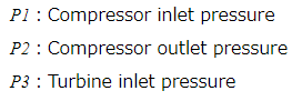
zeta = P3-P1 P2-P1 ···························· (1)
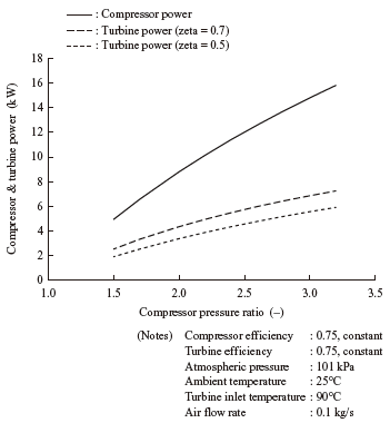
The recovered power changes depending on the specifications and operation point of the FC stack. With the optimal combination of compressor and turbine for the operation conditions, it is possible to recover about 30% of compressor power with the turbine. This enables downsizing of the motor and inverter.
Figure 6 shows the results of comparison of the compression system efficiency indicated by Equation (2) with and without a turbine.
Compression system efficiency = Theoretical adiabatic compression power Inverter input electric power ···························· (2)
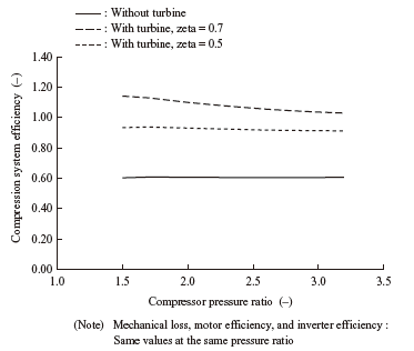
The figure shows that the compression system efficiency with a turbine is far higher than that without a turbine. When zeta is 0.7 and the compressor pressure ratio is 3.0, the compression system efficiency increases from 0.60 to 1.03. Enhancing the compression system efficiency with an electric compressor with a turbine leads to increasing the power that can be used by the fuel cell system.
3.2 Comparison between ETC and two-stage compressors
Figure 7 shows the system flows of a single-stage ETC and two-stage compressor with an intercooler (without a turbine). The inlet temperature of the humidifier in the fuel cell system must be kept below about 100°C, and therefore, both of the compressor systems must have an aftercooler. Furthermore, the two-stage compressor system must have an intercooler to protect the compressor on the high pressure stage side and reduce the compression power. Here, both the intercooler and aftercooler are heat exchangers. However, providing an intercooler in addition to an aftercooler increases the load on the cooling system. As a result, the total size of the heat exchangers of the two-stage compressor increases and can be almost twice as big as the aftercooler of the single-stage compressor(5). Moreover, the increased total pressure loss in the heat exchanger leads to reduced compression system efficiency. Covering the operation point with a single-stage compressor enables the downsizing of the heat exchanger and piping system and the reduction of the pressure loss.
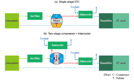
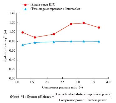
Figure 8 shows the system efficiency of the single-stage ETC and two-stage compressor without a turbine. The figure shows that the ETC has higher efficiency than the two-stage compressor throughout the entire range. When the compressor pressure ratio is 3.2, the system efficiency of the two-stage compressor is 0.79, but that of the ETC is 1.19. Adopting an ETC not only enables downsizing and weight reduction but also enhances system efficiency.
4. Elemental technologies
4.1 Air bearings
The contact of foreign matter with the catalyst in the fuel cell causes the fuel cell system performance to deteriorate. To maintain the efficiency of the fuel cell system under actual operation conditions, such catalyst contamination must be avoided. A typical cause of contamination is lubricant mist. Therefore, the fuel cell system must have an oil-free structure.
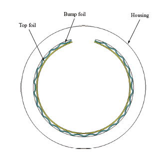
To make the entire system oil-free, IHI’s ETC adopt dynamic pressure air bearings. Two types of air bearings are used: the radial bearing, which supports the rotor in the radial direction, and the thrust bearing, which supports the rotor in the axial direction. Figure 9 shows a schematic cross-sectional view of a radial air bearing as a representative example(6). The radial air bearing consists mainly of a corrugated thin leaf spring (bump foil), a thin plate (top foil), which comes in direct contact with the rotating rotor at low speeds and faces the rotor surface, and a housing, which retains them. Air bearings use air as the lubricating fluid, and therefore, they are usable in environments where no oil can be used and are excellent in maintainability.
While the ETC is off, the rotor and bearings are in contact with each other. When the ETC turns on and the rotor begins rotating, the rotor is rotating in contact with the bearings. When the rotational speed of the rotor increases, a layer of air forms between the bearings and rotor, so the bearings and rotor are no longer in contact with each other. The rotor always rotates in this non-contact state except immediately after the ETC turns on and immediately before it turns off. For IHI’s air bearings, a coating is applied to the sliding surface so that they can rotate and slide while they are temporarily in contact with the rotor when the ETC turns on and off. This enables stop/start operation of the ETC.
The assembly process of air bearings is complex because the thin bump foils and the top foils are inserted to the housing while deformation. The air bearing has been assembled manually, but we are developing a dedicated assembly system, aiming to automate the assembly process for mass production.
4.2 Rotor
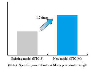
The rotor of the ETC obtains the rotating power mainly from the internal magnet. The new model (ETC-M) has higher motor and compressor power with an increased magnet volume in order to support more powerful FC stacks than the existing model (ETC-S). The increased magnet volume provides increased motor power, but also has adverse effects, such as increased shaft vibration due to increased rotor length and increased stress due to an increased outside diameter. Therefore, we designed the ETC-M by quantifying the degree of each effect to find out the point at which we could achieve higher power, small shaft vibration, and adequate strength. ETC-M is compact in size for both the rotor and the entire body thanks to its higher maximum rotational speed than that of the existing model. We optimized the size, rotor dynamics, and strength design, thereby increasing the specific power of the rotor by 1.7 times as shown in Fig. 10.
4.3 Motor
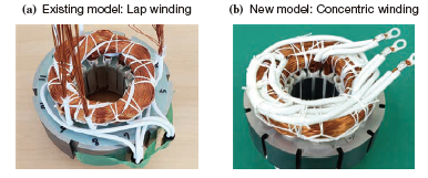
Figure 11 shows the winding method of the motor. For ETC-S, the lap winding method was adopted. The lap winding is superior in terms of performance and size, but automation is difficult, so the lap winding cannot be adopted for the ETC-M, which is intended for mass production. For this reason, the concentric winding has been adopted for ETC-M, in which coils of each phase are arranged radially. This has enabled automatic insertion with an inserter, making mass production possible. In addition, ETC-M has achieved a motor power of 20 kW with a 19% higher rotational speed and about 1.6 times higher torque than ETC-S.
4.4 Inverter
Figure 12 shows the inverters of ETC-S and ETC-M. ETC-M uses a metal-oxide-semiconductor field effect transistor (MOSFET) module using a new material, silicon carbide (SiC), as a power device while ETC-S uses a silicon (Si) insulated gate bipolar transistor (IGBT) module. By changing the device, the inverter efficiency of ETC-M improved by 4%. In addition, by increasing switching frequency, ETC-M has a reduced part size and improved motor efficiency. The DC link capacitor (the part that suppresses the pulsation of DC voltage at power semiconductor switching) has been downsized to about 40% in volume, and the package has been optimized mainly through modification of the board layout.
As the output of fuel cell systems increases, the required maximum voltage is increasing. Therefore, the rated voltage of each part has been upgrade to form an 800 V class system.
5. Conclusion
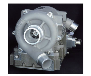
This paper has introduced a new ETC for fuel cells that we developed to meet various fuel cell system requirements.. Figure 13 shows ETC-M. ETC-M has 58% higher power density than ETC-S and provides higher fuel cell system efficiency through power recovery with a turbine. In addition, ETC-M has improved manufacturability for mass production.
Fuel cell systems are actively being developed toward the realization of carbon neutrality. We will contribute to developing a highly efficient system through ETC development, thereby realizing a sustainable society.
REFERENCES
(1) European commission:A Hydrogen Strategy for a climate neutral Europe,2020
(2) Ministry of Economy, Trade and Industry : Ministry of Economy, Trade and Industry Initiatives Toward the Realization of a Hydrogen Society, 2020 (in Japanese)
(3) IHI Corporation: IHI Integrated Report 2021, 2021
(4) Japan Automobile Manufacturers Association : Challenges and Initiatives toward Carbon Neutrality in 2050, 2021 (in Japanese)
(5) D. Filsinger, G. Kuwata and N. Ikeya:Tailored Centrifugal Turbomachinery for Electric Fuel Cell Turbocharger,Hindawi Journal,2021