Development of Circulating Fluidized Bed Thermal Energy Storage (CFB TES) System
ISHIKAWA Atsushi, LIU Zhihong, HASHIBA Michitaro, YAMANE Yoshiyuki, ONIZUKA Hisakazu
ISHIKAWA Atsushi : Doctor of Engineering, Manager, Energy Conversion Department, Technology Platform Center, Corporate Research & Development Division
LIU Zhihong : Doctor of Engineering, Consulting Manager, Energy Conversion Department, Technology Platform Center, Corporate Research & Development Division
HASHIBA Michitaro : Ammonia Gas Turbine Development Department, Resources, Energy & Environment Business Area
YAMANE Yoshiyuki : Doctor of Engineering, Manager, Energy Conversion Department, Technology Platform Center, Corporate Research & Development Division
ONIZUKA Hisakazu : Manager, Energy Conversion Department, Technology Platform Center, Corporate Research & Development Division
Green electricity derived from renewable energy is essential for achieving carbon neutrality. Since the output of renewable energy is unstable, energy storage is required to ensure a stable supply, but the energy storage systems currently in use have drawbacks such as high cost, location constraints, and resource constraints. To solve these problems, IHI, in collaboration with Tsinghua University, developed a thermal storage system that utilizes fluidized bed technology as a large-scale, inexpensive energy storage system. The heat storage material used was silica sand, which is a heat medium commonly used in fluidized bed boilers. After conducting preliminary experiments and analyses, we performed a 100 kW class proof-of-concept (PoC) test and confirmed the effectiveness of the system.
1. Introduction
With the global promotion of efforts to achieve carbon neutrality, there has been an accelerated shift in energy sources from fossil fuels to renewable energy. In Japan, the government declared its goal to achieve carbon neutrality by 2050, and the Agency for Natural Resources and Energy took a leading role in establishing the Green Growth Strategy in June 2021.
Renewable energy sources (photovoltaic and wind power generation), which are expected to be the main power sources in a carbon-neutral society, have achieved significant reductions in power generation costs through increased generation capacity and mass production of devices. However, they have the disadvantages of being heavily dependent on regional characteristics and experiencing large fluctuations in power generation amounts and period of time. Thus, utilizing renewable energy sources requires output stabilization. Energy storage systems are effective for stabilizing renewable energy sources, and typical examples of such systems include storage batteries (secondary batteries), pumped hydro storage and hydrogen utilization system. These systems are important elements in achieving carbon neutrality but have not been widely adopted for various reasons. For example, storage batteries, particularly lithium-ion batteries, have seen progress in cost reduction alongside the widespread adoption of electric vehicles, but the costs of some have shown signs of having bottomed out. Additionally, the globally uneven distribution of the rare metal resources used in lithium-ion batteries to a few specific countries has led to country risk. Pumped hydro storage power generation, which has been used for a long time as a large-scale energy storage system domestically and internationally, has faced difficulty in ensuring sufficient power generation capacity in a timely manner in response to the rapid promotion of power generation from renewable energy sources in recent years. This is due to the formalities that require 15 to 20 years from planning to construction, including the investigation of ideal locations, seeking acceptance from local municipalities, and coordination with relevant ministries and agencies(1), (2). Hydrogen utilization, for which research, technical development and business development have been promoted globally, particularly in Europe, as a prospective means of energy storage and transport, faces the following challenge. To achieve widespread adoption of hydrogen produced using renewable energy (green hydrogen) as an alternative fuel, costs must be reduced. According to the Green Growth Strategy(3), there is a goal to lower the cost of hydrogen power generation to below that of gas-fired power by 2050 and achieving this goal is expected to take a couple of decades.
In addition to the above, storing electricity as thermal energy through thermal energy storage can be another means to stabilize power output from renewable energy sources. Compared to other energy storage methods, thermal energy storage has advantageous characteristics that facilitate cost reduction on a larger scale. The circulating fluidized bed thermal energy storage (CFB TES) system introduced in this paper has the potential to address the issues of existing energy storage systems.
First, the system does not use rare metals, unlike storage batteries, thereby lowering any country risks associated with procuring raw materials. In terms of costs, the thermal storage system is highly compatible with existing steam turbine power plants, significantly reducing the costs of thermal energy storage systems by repurposing power generation facilities that have been forced to shut down due to the shift toward decarbonization and the deterioration of boilers. Repurposing steam turbines is also advantageous in terms of stabilizing electric power systems. It has been said that variable renewable energy sources, such as photovoltaic and wind power generation, lack the inertial and synchronous capabilities possessed by conventional thermal and hydro power generation. Inertial and synchronous capabilities are essential elements for maintaining a stable supply of electric power, even in the event of an electric power system failure. There has been concern that the large-scale introduction of variable renewable energy sources could lead to a shortage of the inertial capability needed to maintain the stability of electric power systems. In contrast, the CFB TES system possesses inertial and synchronous capabilities, thereby supporting the widespread adoption of renewable energy sources while ensuring the stability of electric power systems. Additionally, the CFB TES system has advantages over pumped hydro storage power generation. This is because it can be constructed near areas with high energy demand, with minimal locational constraints, and can be built within short time frames, allowing for flexible adjustment of power generation capacity to accommodate the increasing adoption of renewable energy.
Following discussions in its “Study Group for Energy Storage Technologies Toward Carbon Neutrality (in Japanese),” the Japan Society of Mechanical Engineers (JSME) expressed the importance of thermal storage technologies in achieving a carbon-neutral society as a recommendation from JSME(4).
In contrast, storing energy in the form of heat has the disadvantage of low electric power output efficiency (round trip efficiency) relative to input electric power. To address this disadvantage, it is essential to directly utilize the stored heat. Since heat is more difficult to transport than electricity, it is assumed that the heat storage systems should be installed in locations close to consumers for effective use of heat. The CFB TES system is best suited for applications involving consumers that require both electricity and heat or those that demand large quantities of high temperature heat. Existing heat consumers are likely to rely more on inexpensive fossil fuel than on electricity as an energy source. It has been recognized that using green fuel (produced from renewable energy sources) is important for decarbonizing heat utilization. Nevertheless, it is current situation that the decarbonization of heat utilization has not progressed due to the low cost of thermal energy itself. In contrast, the demand for inexpensive energy storage systems has increased due to the sharp rise in fossil fuel prices triggered by recent global instability and the intensifying global trend toward decarbonization.
This paper introduces the concept of the CFB TES system as a large-scale, inexpensive energy storage solution capable of contributing to the decarbonization of electricity and heat. It also presents the results of elemental technology development and a proof-of-concept (PoC) test.
2. System concept
2.1 System components
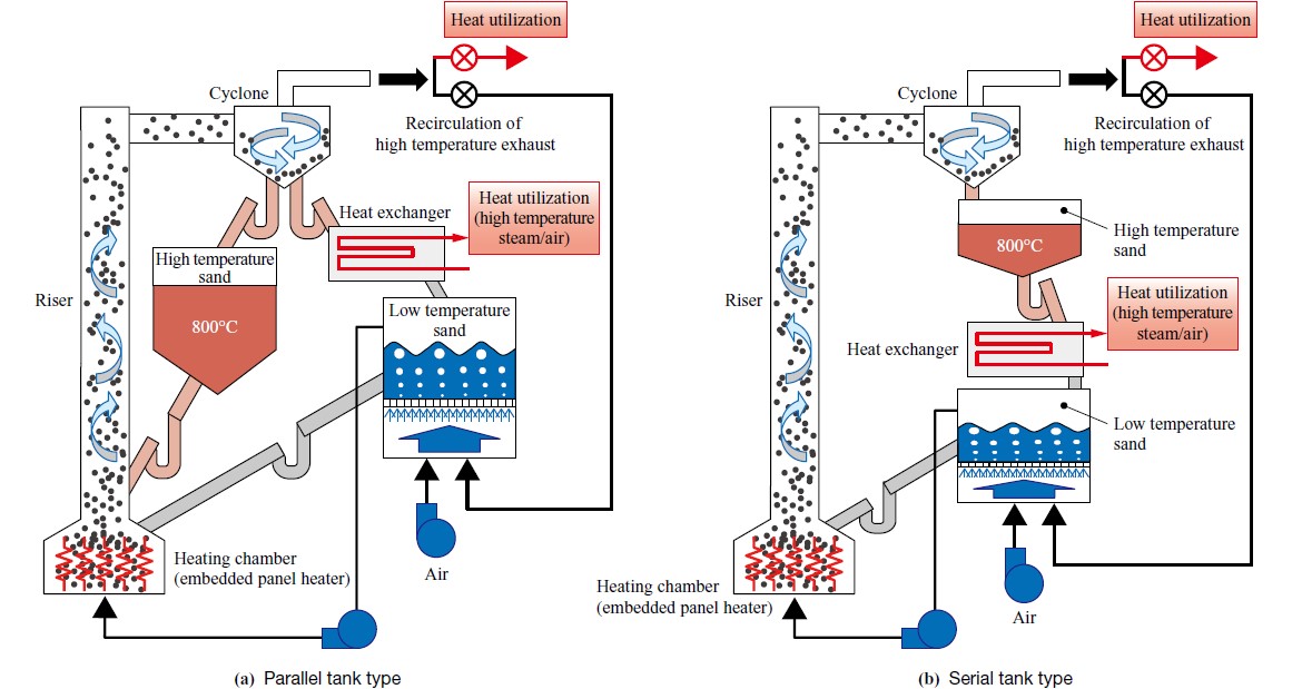
The development concept of the system is to create a large-scale, inexpensive energy storage solution that enables the effective and stable utilization of electricity generated from renewable energy sources. This is achieved through technologies that convert electric energy, which is low cost on a global scale, into thermal energy using electric heaters, and sand is heated by the converted thermal energy to store it. This system is based on technologies used in circulating fluidized bed (CFB) boilers. When energy demand arises, it produces steam by heating water with the thermal energy stored in sand and utilizes the steam for power generation with steam turbines or for industrial processes. Figures 1 and 2 show a conceptual diagram and schematic configuration diagram of the CFB TES system respectively. Depending on the arrangement of the sand storage tanks, the system configuration is classified into two types: the parallel tank type (Fig. 1-(a) and Fig. 2-(a)) and the serial tank type (Fig. 1-(b) and Fig. 2-(b)).
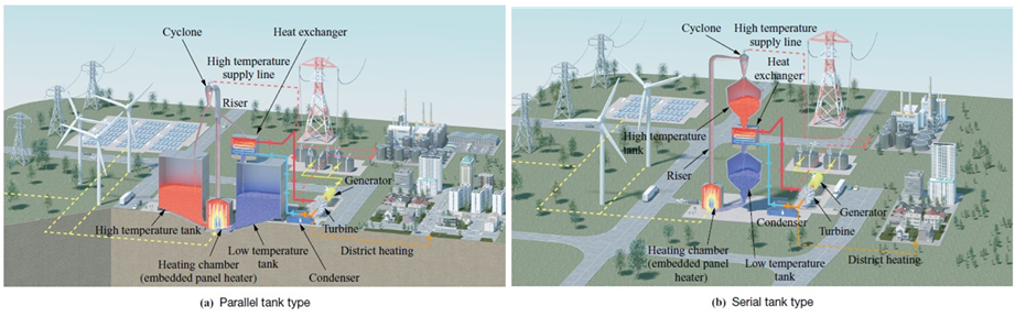
The main system components are a low temperature tank, a high temperature tank, a heating chamber (embedded panel heater), a riser, a cyclone, and a heat exchanger. The functions required for each component are as follows: The low temperature tank stores low temperature sand before thermal storage. The high temperature tank stores high temperature sand after thermal storage and must meet the requirements for heat resistance and heat insulation performance. The heating chamber consists of a plate-like embedded panel heater and wall faces surrounding the heater. The embedded panel heater is an electric heater that heats the sand and must do so effectively within a limited space. The riser is piping to transport the sand heated in the heating chamber to a tank and must meet the requirements for heat resistance and heat insulation performance. The cyclone separates sand from the air carrying it and must meet the requirements for both separation performance and abrasion resistance. The heat exchanger exchanges heat between high temperature sand and water or air to generate steam or high temperature air.
2.2 Operation method and applications of the CFB TES system
The operation method of the CFB TES system has three modes: the charge mode to store energy, the wait mode to retain stored energy, and the discharge mode to extract energy for use when needed. Since there is no sand movement involved in the wait mode, the following explanation will focus on the charge and discharge modes, where sand movement occurs.
In the charge mode, electric energy is converted into thermal energy to store it in the sand. The sand is transferred from the low temperature tank to the heating chamber at the bottom of the riser, where it is heated by contacting with the electrically heated embedded panel heater. The high temperature sand is then transferred to the high temperature tank via the riser and cyclone by supplying air from the bottom of the heating chamber. The air used to transfer the sand increases in temperature by absorbing heat from both the sand and the heater. The heat of the high temperature air separated from the sand in the cyclone is used to preheat the air supplied to the heating chamber, thereby improving the efficiency of the entire system.
In the discharge mode, the thermal energy stored in the sand is extracted as high temperature air or steam which can be used in downstream processes. In the case of the parallel tank type as shown in Fig. 2-(a), the sand extracted from the high temperature tank is supplied to the heat exchanger via the heating chamber, riser, and cyclone. The heat of the high temperature air exhaust from the cyclone outlet is used to preheat the conveying air, similar to the charge mode. In contrast, in the case of the serial tank type, as shown in Fig. 2-(b), the sand from the high temperature tank is supplied directly to the heat exchanger below the tank. The high temperature sand supplied to the heat exchanger loses heat to water or steam and is then stored in the low temperature tank. The charge mode and discharge mode can be operated in parallel, depending on the operating methods of the application side. In the case of the parallel tank type, as shown in Fig. 2-(a), the sand downstream of the cyclone is distributed to both the sand stored in the high temperature tank and the sand supplied to the heat exchanger. In the case of the serial tank type, as shown in Fig. 2-(b), while storing sand from the top of the high temperature tank, the sand is supplied to the heat exchanger from the bottom.
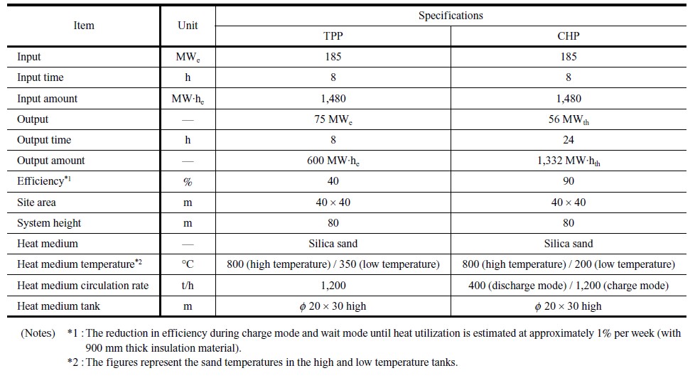
The potential applications of this system include thermal power plants and combined heat and power plants that have steam turbines. In these applications, during the transition to a carbon-neutral society, the quantity of steam from the CFB TES system can be gradually increased while maintaining the plant’s functionality, similar to coal-fired thermal plants transitioning to ammonia as a fuel. Table 1 presents the assumed specifications for the system’s input, output, and scale. The assumed operation involves storing inexpensive electrical energy from renewable sources for 8 h, and supplying steam for 8 h in the case of the thermal power plant (TPP) or supplying steam for 24 h in the case of combined heat and power (CHP) plant.
3. Development of components
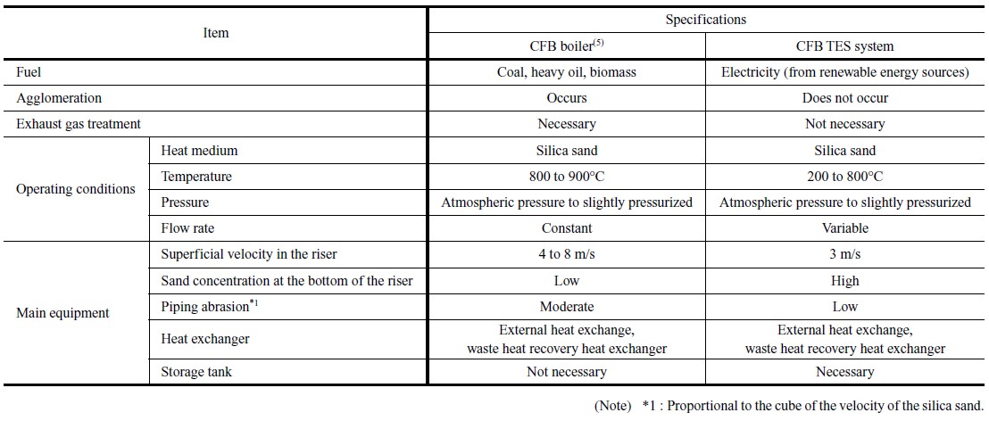
This CFB TES system is based on technologies used in CFB boilers. Table 2 shows the differences between a general CFB boiler and the CFB TES system. Using electricity as the heat source for the circulating fluidized bed thermal storage offers the advantage of eliminating the need for measures against agglomeration caused by local overheating of carbon-hydrate-based fuels and the treatment of exhaust gases. In contrast, it requires a method to efficiently transfer heat from the heater to the sand in the heating chamber and an operation to dynamically control the flow rates of the circulating sand. In the following sections, Section 3.1 explains the embedded panel heater, while Section 3.2 discusses the development status of the particle flow rate control mechanism.
3.1 Heating chamber (embedded panel heater)
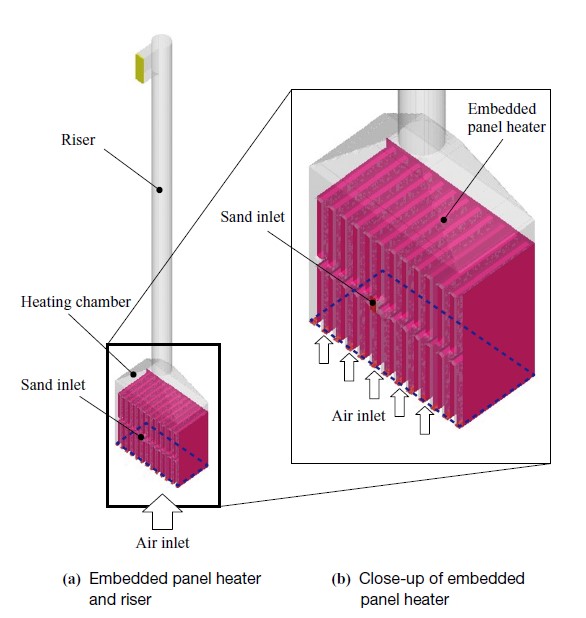
The energy sources for CFB boilers are coal and biomass fuel fed into the fluidized bed, whereas the energy source for the CFB TES system is a plate-like heater installed within the fluidized bed. Figure 3 shows a schematic diagram of the embedded panel heater. It is positioned on the upper surface of a distribution plate that supplies air to the bottom section of the riser. The sand, input through an inlet on the side wall, flows into the gaps in the embedded panel heater and forms a region with a high particle concentration (a region where a dense particle phase forms a continuous phase) around the heater. Air is uniformly supplied to the region through the distribution plate at the bottom of the heater. Similar to a bubbling fluidized bed, the sand around the embedded panel heater is agitated by being pushed upward and outward, or sucked upward by the upward airflow, while flowing downward in the local areas near the wall surfaces where air (bubbles) is stagnant. The sand in the region above the embedded panel heater with a low particle concentration is carried by the air to the riser. Being agitated around the embedded panel heater, the sand frequently comes into contact with the heater, allowing the heat to effectively transfer to the sand. Reducing the thickness and panel spacing of the embedded panel heater can compact the heating section, thereby reducing the required footprint and minimizing heat loss due to radiation. In contrast, excessively narrow panel spacing may create local areas that obstruct smooth sand flow. Additionally, increased contact with the sand may accelerate the abrasion of the heater. In addition to contact frequency, the parameters affecting abrasion include the material characteristics of the particles and wall surfaces (such as hardness and brittleness), impact velocities of the particles, impact angles, and temperature.
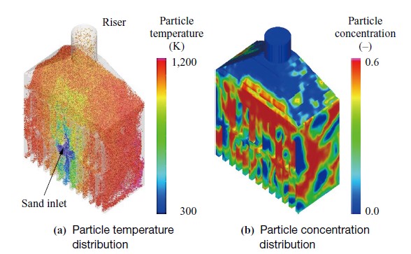
From the above perspectives, the important functions of the embedded panel heater are: (1) preventing the formation of local areas with excessively high temperatures by allowing the sand to flow smoothly from the inlet to the riser without stagnating in narrow sections, and (2) limiting abrasion to a level that does not cause serious problems. The numerical analyses were conducted to evaluate these functions. The analysis tool used was Barracuda (Virtual Reactor With Chemistry, CPFD Software), which was developed specifically to predict the flow phenomena of highly concentrated particles. The tool uses the Eulerian method and the Lagrangian method to analyze fluid phase and solid particles respectively. To reduce the computational load, the interactions among particles were calculated using a model based on the volume fractions within the computational cells. The analysis conditions included a required heater surface temperature of 1,000°C to heat the sand to 800°C. An example of the analysis results is shown in Fig. 4. Figure 4-(a) shows the temperature distribution of particle clusters. In the figure, red dots indicate high temperature areas, while blue dots represent low temperature areas. According to the figure, the sand temperature is low near the sand inlet and increases to approximately 800°C as it is heated by the heater in the area near the sand outlet (or the riser inlet). Figure 4-(b) shows the distribution of particle concentrations. In the figure, red dots represent areas with high concentration. According to the distribution, it was confirmed that the sand and air were evenly mixed and flowed smoothly through the narrow space around the heater without forming regions where the sand drifted, became occluded, or stagnated. It was also confirmed that, since the flow velocity was slower than that of general CFB boilers, the amount of abrasion was limited.
3.2 Particle flow rate control mechanism
The CFB TES system requires flexible control of particle flow rates in both the charge and discharge modes. Typically, a screw feeder is used as a flow rate control device for transporting particles. However, it is not suitable for transporting high temperature particles. Additionally, the J-type and L-type valves, designed for transporting high temperature particles, regulate particle flow solely through on-off control. In this research, an apparatus capable of controlling the flow rates of high temperature particles was developed by installing an orifice upstream of a loop seal (J-type valve), which is widely used in circulating fluidized beds.
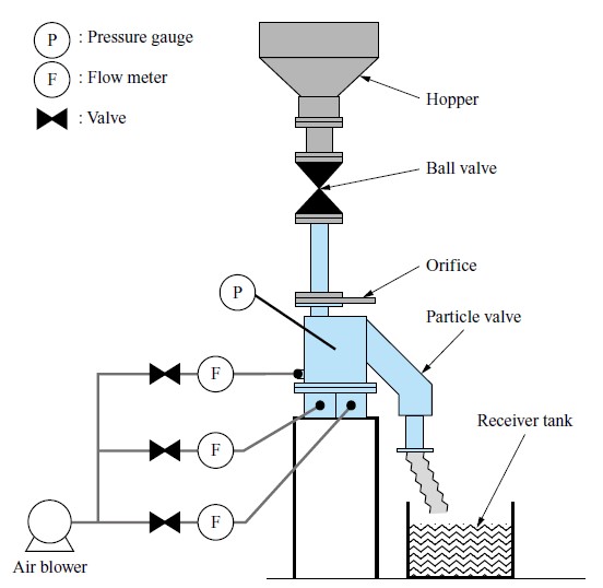
Figure 5 shows a schematic diagram of the experimental apparatus. In this setup, sand was supplied from a sand storage hopper to the orifice and particle valve via a ball valve and piping, and was eventually discharged into a receiver tank at the bottom. Sand can be fluidized by introducing air into the wind box at the bottom of the particle valve. In the experiment, the following aspects were evaluated: (1) the ability to control the particle flow rate at a constant value using the orifice and particle valve, and (2) the flow resistance of the particle valve by comparing experimental results between particle flow through the orifice alone and particle flow through both the orifice and the particle valve. Furthermore, in the actual system, the outlet of the valve in the apparatus is connected to the embedded panel heater at the bottom of the riser. This structure causes the flow rate control to be influenced by back pressure. It is well known that high back pressure on the outlet side increases flow resistance(5). Therefore, the influence of outlet pressure on flow rate control was included as evaluation item (3). The results are shown below.
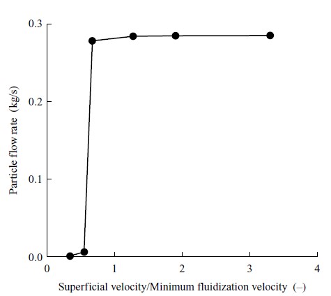
- Figure 6 shows the relation between particle flow rates and fluidizing air velocities. The horizontal axis represents the normalized superficial velocities, calculated by dividing the air velocity during no-substance conveyance by the minimum fluidization velocity, which is the air velocity at the onset of fluidization. The larger the value of the normalized superficial velocity, the greater the air flow rate, and the more fluidized the sand becomes. According to the experimental results, it was confirmed that particle flow rates can be controlled to a constant value by supplying more than a certain volume of fluidizing air.
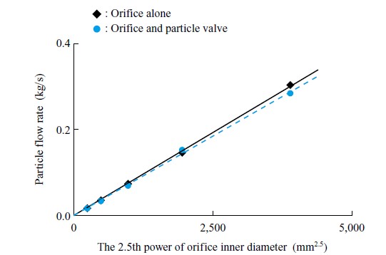
- Figure 7 shows the experimental results of the effects of the orifice diameter and the presence or absence of the particle valve on particle flow rates. According to the research by Shirai, particle flow rates inside piping are proportional to the 2.5th power of the piping diameter(6). The experimental results in this research also confirmed the linear relation between the 2.5th power of the orifice diameter on the horizontal axis and the particle flow rates on the vertical axis. Additionally, the experimental results showed that the reduction in the particle flow rates due to the presence of the particle valve was approximately 4%. Based on these experimental results, the flow resistance of the particle valve is significantly smaller than that of the orifice, allowing the orifice to control the sand flow rate at a constant value. In the actual apparatus, multiple valves are connected in parallel to discretely control the particle flow rate.
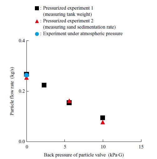
- Figure 8 shows the relation between the back pressure of the particle valve and particle flow rates. The figure shows the experimental results under atmospheric and pressurized conditions. In the experiment under pressurized conditions, measuring particle flow rates required some consideration because the downstream side of the particle valve was sealed off in a pressurized tank. Thus, the figure shows the increase in weight of a tank after allowing the sand to flow into it for a certain period (pressurized experiment 1) and the readings of the rate of sedimentation of the interface between the sand and air in the transparent visualization piping upstream of the orifice (pressurized experiment 2). Both experimental results showed a trend in which particle flow rates decreased linearly with the increase in back pressure of the particle valve. Additionally, under the condition of high back pressure of the particle valve, it was observed that the air in the pressurizing tank flowed backward into the particle valve causing unstable sand flow.
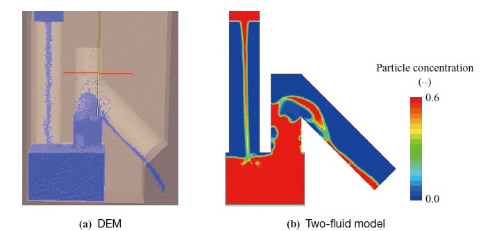
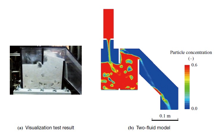
In addition to these experiments, a CFD analysis was conducted with the goal of understanding flow phenomena inside the particle valve and acquiring particle valve design techniques. Typical analysis methods for solid-gas multiphase flows are twofold: the discrete element method (DEM), which uses a physical model to precisely analyze the behavior of each particle, and the two-fluid model, which treats a dense layer of sand as a continuum. DEM considers the behavior of each particle and the collisions between particles. While it offers high reproduction accuracy of physical phenomena, it has the disadvantage of a high computational load. In contrast, the two-fluid model does not model the behavior of individual particles, but models them as a fluid. Compared to DEM, the two-fluid model is characterized by a lower computational load, although its prediction accuracy for particle behavior is lower. In particular, the two-fluid model is well-suited for predicting flow fields where a highly dense particle cluster behaves like a fluid. In this research, a comparison was made between the analysis results of particle flow inside the particle valve using DEM and the two-fluid model. Subsequently, the applicability of the two-fluid model to particle valve design was evaluated. Figure 9 shows one example of analysis results. Figure 9-(a) presents the analysis result using DEM (iGRAF by Kozo Keikaku Engineering Inc.), while -(b) shows the analysis result using the two-fluid model (Ansys Fluent by ANSYS, Inc.). The two-fluid model is based on the Euler-Granular method for particle multiphase flows. While DEM is a three-dimensional model, the two-fluid model in this study employs a two-dimensional model for convenience when conducting parameter studies under various conditions. Thus, although the comparison of simulation results between the two methods was qualitative, important characteristics of particle flows were confirmed. These include the orifice’s ability to control particle flow rates, the formation of a particle-free space downstream of the orifice, and the intermittent blowing and discharge of particles. Subsequently, as shown in Fig. 10, these analysis results were compared with the result of the visualization experiment. Along with the comparison of experimental results under various conditions with atmospheric pressure at the outlet of the particle valve, these comparisons clarified particulate flow phenomena, including the reduction in flow rates due to pressurization on the downstream side of the particle valve, intermittent changes in flow rates, and backward airflow from the downstream side. Accordingly, it was confirmed that the two-fluid model can be applied to the flow analysis for designing the particle valve.
4. Demonstration test
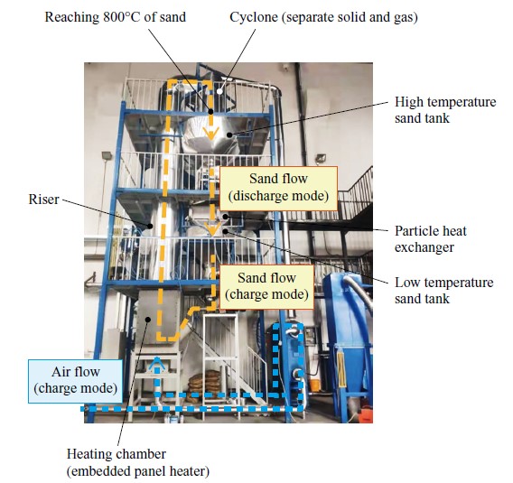
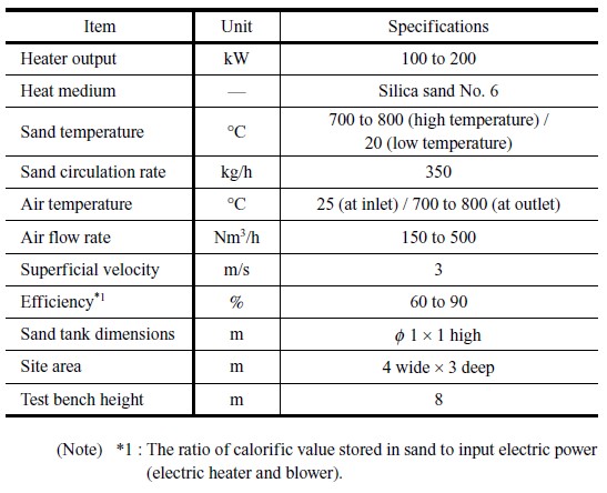
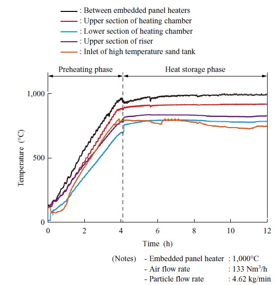
A 100 kW class test bench was fabricated, and a demonstration test was conducted to demonstrate the principle of the CFB TES system. The demonstration test was conducted with the cooperation of Tsinghua University. To effectively promote the development of the system, the demonstration test was conducted with a focus on the differences from existing CFB boilers. Specifically, the test focused on demonstrating the functionality of heating sand with the embedded panel heater and transporting high temperature sand from the heating chamber to the tank. Figure 11 shows the external appearance of the test bench. The test bench was based on the serial tank type as shown in Fig. 2-(b). Table 3 summarizes the specifications of the test bench. The demonstration test results are shown in Fig. 12. The test demonstrated the system’s principle by stably heating the sand to 800°C, with the surface temperature of the embedded panel heater set to 1,000°C, and successfully storing heat in the high temperature sand tank.
5. Conclusion
Regardless of whether they are used domestically or internationally, large and cost-effective energy storage systems are essential for decarbonizing heat and electricity usage by maximizing the potential of renewable energy sources with fluctuating outputs, aiming to achieve a carbon-neutral society. In this research, the circulating fluidized bed thermal energy storage system was developed as a solution for achieving decarbonization in heat and electricity usage, based on the technologies of circulating fluidized bed boilers. After developing techniques primarily for elements not included in existing circulating fluidized bed boilers, a demonstration test was conducted to demonstrate the principle of the entire system using a 100 kW class test bench. As a result, it was confirmed that input electricity can be stored in sand heated to 800°C. In the future, IHI will continue developing the circulating fluidized bed thermal energy storage system for social implementation and commercialization, with the goal of making it a solution beneficial to customers, IHI, and society as a whole.
- ― Acknowledgments ―
- The demonstration test using the 100 kW class PoC test bench was conducted with much cooperation from Tsinghua University. It was successfully carried out thanks to the technical support of Professor Hai Zhang, Associate Professor Yang Zhang, and the cooperation of many outstanding students. We would like to express our deep gratitude for their support and cooperation.
REFERENCES
(1) Kyushu Electric Power Co., Inc. : Necessity of Omarugawa Power Plant and its Development History, https://www.kyuden.co.jp/company_history_energy_hydropower_hydropower.html,(accessed 2024-03-16 (in Japanese))
(2) Engineering Advancement Association of Japan : Construction Work of Kyogoku Power Plant for Hokkaido Electric Power Co., Inc.,https://www.enaa.or.jp/GEC/nec/html/nyokai/sk06-8.pdf,(accessed 2024-03-16 (in Japanese))
(3) Ministry of Economy, Trade and Industry : Green Growth Strategy Through Achieving Carbon Neutrality in 2050,https://www.meti.go.jp/english/policy/energy_environment/global_warming/ggs2050/pdf/ggs_full_en1013.pdf accessed 2024-03-16
(4) The Japan Society of Mechanical Engineers : Proposal for the Best Energy Storage Mix to Achieve Carbon Neutrality (2024), https://www.jsme.or.jp/about/about-jsme/proposal/teigen202404/accessed 2024-03-16 (in Japanese)
(5) M. Horio and S. Mori : Fluidization Handbook edited by the Association of Powder Process Industry and Engineering, Japan, Baifukan, 1999 (in Japanese)
(6) T. Shirai : Outflow Velocity of Power from Orifice, Chemical Machinery, Vol. 16, No. 3, 1952, pp. 86-89 (in Japanese)