Technologies for Replacement of Bridge Slabs
SAITO Shiro, MUTAGUCHI Takusen, TAKAGI Yusuke, YAMAZAKI Toshihiro, IKEGAMI Kotaro
SAITO Shiro : P.E.Jp, Manager, Research and Development Department, New Business Promotion Division, IHI Infrastructure Systems Co., Ltd.
MUTAGUCHI Takusen : P.E.Jp, General Manager, Research and Development Department, New Business Promotion Division, IHI Infrastructure Systems Co., Ltd.
TAKAGI Yusuke : Business Development Department, Bridge Division, IHI Construction Service Co., Ltd.
YAMAZAKI Toshihiro : P.E.Jp, General Manager, Steel Bridge Renewal Design Department, Bridge Division, IHI Construction Service Co., Ltd.
IKEGAMI Kotaro : P.E.Jp, General Manager, Business Development Department, Bridge Division, IHI Construction Service Co., Ltd.
As bridges in Japan are aging, replacement works are conducted for slabs directly subjected to the load of passing vehicles. Many works conducted so far did not have much difficulty caused by bridge conditions, but more and more difficult works must be conducted in the future. In order to complete such works with a variety of severe conditions, the IHI Group has developed technologies for facilitating replacement of slabs. This paper introduces these technologies briefly.
1. Introduction
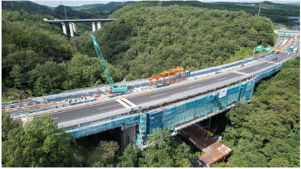
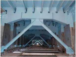
Many of the road bridges in Japan were constructed during the period of Japan’s rapid economic growth from the 1950s to the 1970s, and they have been in service for more than half a century. Floor slabs (slabs that transfer the loads from vehicles passing over bridges) of the steel bridges constructed in those years tend to be less durable than those of bridges designed and constructed to stay in service for 100 years as assumed under the current standards revised in 2017(1). Because there are bridges that are showing signs of deterioration or damage, floor slab replacement work is currently in progress in many regions of Japan. Figure 1 shows slab replacement work at Fukazawa Bridge on the Chuo Expressway of Central Nippon Expressway Company Limited (NEXCO CENTRAL). Floor slab replacement works that have been carried out so far have mainly involved bridges on relatively small roads that can be completely closed to traffic all day without major social impact or easy-to-construct standard bridges without headroom restrictions. The coming years, however, are likely to see more slab replacement works in which construction work needs to be carried out under more challenging conditions. For example, bridges can only be closed at night due to traffic restrictions, or on special-design bridges that are technologically difficult to construct, such as arch bridges and truss bridges.
To meet diverse construction needs in the years to come, the IHI Group is working on the development of various bridge slab replacement technologies. This paper introduces slab replacement equipment, replacement slabs and technologies for slab replacement.
2. Slab Replacement Equipment
With the aim of meeting challenging construction needs, such as replacing the slabs of an in-service bridge that cannot be completely closed to traffic during slab replacement or carrying out slab replacement at a site where overhead high-voltage transmission lines impose headroom restrictions, the new slab replacement equipment described below has been developed.
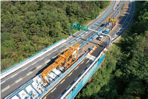
2.1 EVO
In cases where the slabs of a bridge on a road that cannot be completely closed to traffic due to social impacts are to be replaced, it is necessary to divide the bridge width into several sections and carry out slab replacement lane-by-lane. To make such slab replacement possible, slab replacement equipment designed specifically for lane-by-lane slab replacement, EVO, has been developed. Figure 2 shows the slab replacement equipment EVO that enables lane-by-lane slab replacement. EVO is approximately 19 m long and has a main body width of approximately 3.7 m (the gate-shaped orange machine that can be seen at the center of Fig. 2). EVO is placed at the construction location, and three precast prestressed concrete (PCaPC) slabs are replaced there. Then, EVO is moved to the next placement location, and this cycle is repeated. The gross weight of the slab replacement equipment including all accessories is approximately 21.5 t. This is less than half of the weight of a 50-t crawler crane, which is typically required in the conventional construction method.
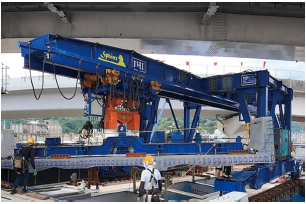
2.2 Sphinx
At a site where there are overhead high-voltage transmission lines or in cases where headroom restrictions are imposed by an overhead structure such as an expressway junction, it may not be possible to use a conventional mobile crane. To overcome such problems, lightweight low-profile multi-function slab replacement equipment, Sphinx, capable of speedy slab replacement has been developed. Figure 3 shows a Sphinx, slab replacement equipment capable of performing slab replacement even at a site with limited headroom. The Sphinx is 20.5 m long and 4.3 m high. The Road Structure Ordinance generally requires that vertical clearance under overhead structures such as signs or at grade-separated intersections be 4.5 m or less. With a total height of 4.3 m, Sphinx is capable of carrying out slab replacement without causing any problems at sites with limited headroom such as grade-separated intersections. Since the gross weight of the Sphinx is approximately 47 t, loads on existing girders during slab replacement can be reduced compared with other construction equipment such as a mobile crane. Although slab replacement usually requires the reinforcement of existing steel girders, Sphinx reduces the amount of reinforcement required for slab replacement.
3. Replacement Slabs
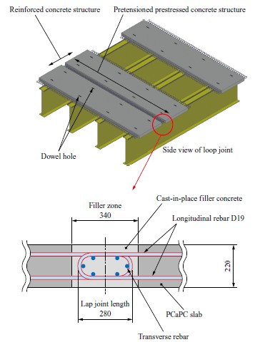
This chapter introduces PCaPC slabs and steel plate decks available as replacements for deteriorating reinforced concrete (RC) slabs. A PCaPC slab is a floor slab constructed by joining together prefabricated precast (PCa) members segmented along the bridge axis (the direction of vehicle movement) into an integral structure at the construction site. PCaPC slabs and steel slabs are advantageous because by replacing RC slabs with more durable PCaPC slabs or steel plate decks, the service life of the bridge can be extended as long as the girders remain structurally sound.
Figure 4 shows a typical PCaPC slab. It is common practice to design a PCaPC slab as a prestressed concrete structure of the pretensioned type in the direction perpendicular to the bridge axis (transverse direction) and as a reinforced concrete structure in the bridge axis (longitudinal) direction. Longitudinal joints are loop joints that join the PCaPC slab segments by use of cast-in-place concrete.
A steel plate deck consists of a steel deck plate reinforced from underneath with longitudinal and transverse stiffening ribs. Figure 5 shows a steel plate deck. Steel plate decks have been used in many places, particularly for bridges built on weak ground and urban viaducts, because of their advantages such as being lightweight compared to concrete-based slabs and having a shorter construction period. Old and deteriorating bridges tend to have been designed to withstand smaller live loads and seismic loads than the current design standards allow for. Therefore, in cases where concrete-based slabs that conform to the current standards are to be adopted, increases in dead loads may necessitate substantial reinforcement of the bridge structure including the substructure. In such cases, using steel plate decks makes it possible to reduce dead loads, eliminate the need for substructure reinforcement, and achieve a shorter construction period.
4. Technologies for Slab/Deck Replacement
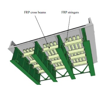
As examples of technologies for slab replacement, this section introduces FS Grid (FRP-supported grid), a method for extending the life of existing slabs by using fiber-reinforced plastics (FRP); Rapid Floor, a newly developed scaffold system designed for enhanced strength, safety and usability; and VanLoc joints that make faster PCaPC slab construction and labor saving possible.
4.1 FS Grid
Figure 6 shows FS Grid, a method for extending the life of existing slabs by using FRP reinforcements. FS Grid is a newly developed technology for extending slab life that can be used at sites where traffic restriction and slab replacement work are difficult to carry out, such as in urban areas. Extending the life of slabs gives road authorities the time needed to adjust the timing of slab replacement work so that the construction workload can be evened out. Its main features are as follows:
- FS Grid is an under-deck construction method involving the installation of reinforcements to the underside of the slab. It is therefore possible to allow vehicles to pass over the bridge while carrying out replacement work over a long period of time without imposing large-scale traffic restrictions, substantially reduce congestion due to long-term traffic restrictions. In addition, it is possible to reduce construction lead time and construction cost because structural members can be fabricated in a relatively short period of time.
- FRP is used for main structural members (cross beams and stringers), and those members are light enough for workers to carry by hand. Consequently, the frequency of use of heavy construction equipment can be reduced so that carbon dioxide (CO2) emissions can be reduced compared with slab replacement.
4.2 Rapid Floor
At construction sites requiring suspended scaffolding, it used to be common practice to use tubular scaffolds consisting of steel pipes and scaffolding boards. In recent years, the use of scaffold systems capable of forming flat work platforms has been on the increase to enhance safety and productivity. Because bridge maintenance work involves handling heavy objects such as replacement members and reinforcing members on working platforms, there is growing demand for scaffold systems that make it possible to provide stronger and larger working platforms.
Figure 7 shows Rapid Floor, a scaffold system designed for enhanced safety and usability. The newly developed scaffold system, Rapid Floor, has a hanging chain span of 1.8 m in both the longitudinal and transverse directions to provide a large work space in the scaffold. With a main truss frame consisting of several triangular subframes and high-strength chains, Rapid Floor is four times stronger than conventional scaffolds. Furthermore, since Rapid Floor is designed to be used with conventional steel scaffold boards, cost can be minimized while retaining a load capacity of 200 kg/m2, which is larger than the capacity of conventional tubular scaffolds.
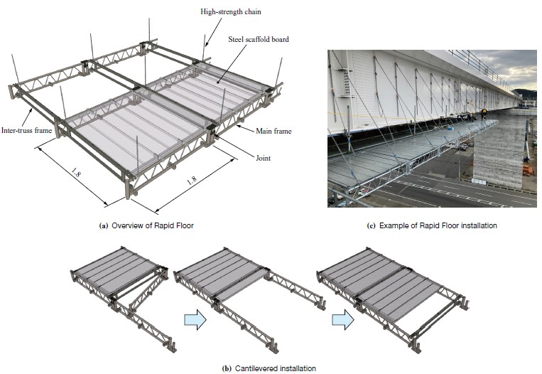
Rapid Floor excels in usability, too, because it can be erected and disassembled as a cantilever structure from a scaffold. The use of aerial work platforms, therefore, can be minimized while achieving enhanced safety, a shorter working period and cost reduction.
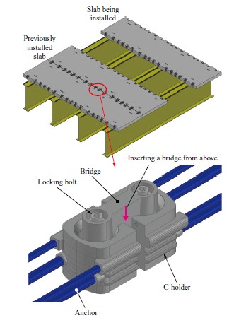
4.3 VanLoc
For floor slab replacement work, there is growing demand for shorter working hours due to traffic restrictions and for labor saving because of a construction worker shortage. Longitudinal connection of PCaPC slabs is usually achieved by using loop joints that utilize the longitudinal reinforcing bars of the PCaPC slabs and placing cast-in-place concrete in filler zones that are approximately 340 mm in width (see Fig. 4). However, since loop joints require reinforcement assembly work in filler zones, formwork assembly work, and concrete placing and curing, the long working hours and increased manpower requirements are posing problems.
Figure 8 illustrates VanLoc, which enables faster connection of PCaPC slabs and labor saving. The newly developed VanLoc joint consists of steel C-holders with longitudinal anchors, and a bridge. VanLoc joints are installed at intervals of 500 mm or less in the direction perpendicular to the bridge axis. The main features of VanLoc are as follows:
- No need of formwork and reinforcement assembly work for the filler zones
- No need for concrete placement
- The number of PCaPC slabs can be reduced (because there are no reinforcing bar protrusions as with loop joints).
- Shorter construction period than conventional loop joints
- By bolting wedge-shaped erection members onto C-holders prior to bridge installation, the slab being installed can be pulled into position toward the previously installed slab.
5. Conclusion
This paper has introduced some of IHI Group’s bridge slab replacement technologies. In order to meet the increasingly demanding requirements of slab replacement work under increasingly challenging construction conditions, we will continue our technology development and practical application efforts contributing to labor saving in slab replacement.
REFERENCES
(1) Japan Road Association : Specifications for Highway Bridges, Part I, Common Specifications, 2017 (in Japanese)