
Performance Analysis Tool for Ball Bearings
ITO Akira, SHIBATA Ai
ITO Akira : Manager, Turbomachinery & Machine Elements Department, Technology Platform Center, Corporate Research & Development Division
SHIBATA Ai : Turbomachinery & Machine Elements Department, Technology Platform Center, Corporate Research & Development Division
Rolling bearings, which are widely used in IHI products, often play a critical role as key components that significantly affect product performance. Therefore, it is essential to estimate and understand their characteristics and performance, such as bearing stiffness and internal stress distribution. To meet the necessity, we are developing an in-house tool to analyze the performance of ball bearings, which are among the most frequently used types of rolling bearings. This paper provides an overview of this tool.
1. Introduction
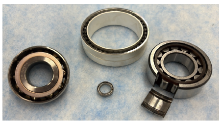
Rolling bearings are used in many IHI products. Figure 1 shows examples of rolling bearings. Their operating environments vary in speed, load, and temperature. In addition, rolling bearings are often used beyond the conditions recommended in general catalogs. Because the performance of rolling bearings may influence product performance, it is important to estimate and understand their performance, shown in forms of bearing stiffness, internal stress and other items, in the context of the use environment. Although tools to analyze the performance of rolling bearings are commercially available, the source code is generally not open to the public, leading to a problem in that the assumptions and theories used are unknown, making it impossible to know the applicability and accuracy. To address this issue, we are developing an in-house analysis tool to analyze the performance of ball bearings, which are among the most frequently used types of rolling bearings.
2. Overview
2.1 Overview of the analysis tool
The calculation targets of this analysis tool are single-row deep groove ball bearings and angular contact ball bearings. The main input and output items are listed in Table 1.
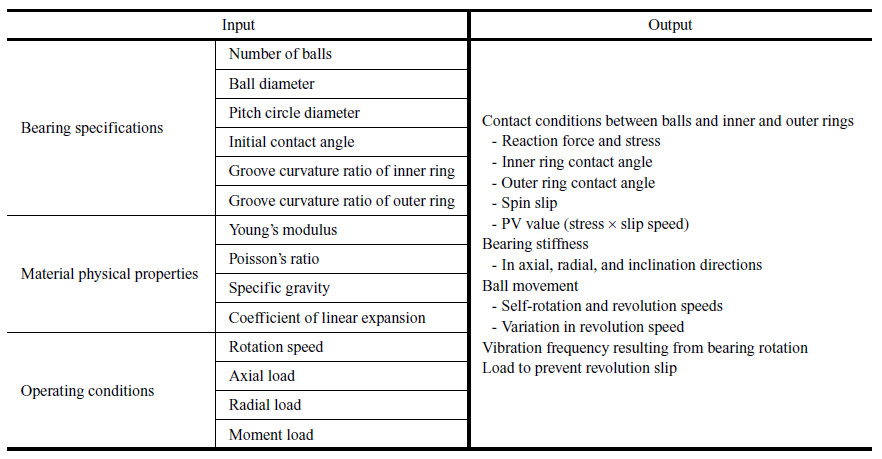
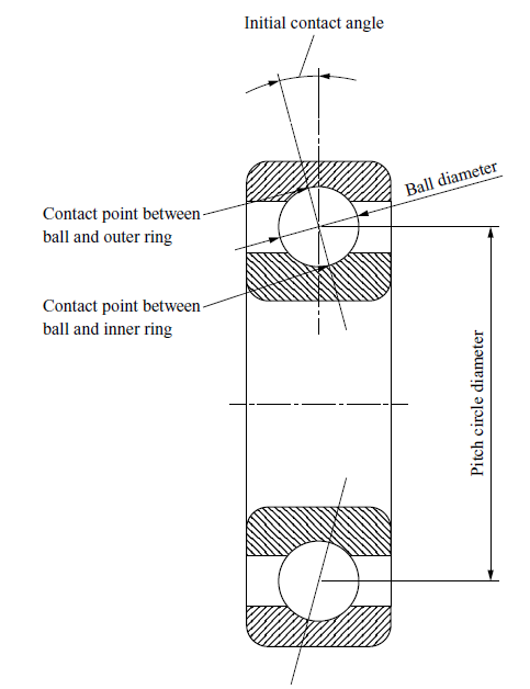
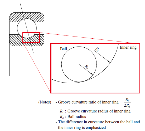
The main input items related to bearing specifications are illustrated in Figs. 2 and 3. Most of these values are available in catalogs or from bearing manufacturers. Unknown values are determined by actual measurements and analogy based on past data.
When a user inputs the design specifications, material physical properties of a bearing and its operating conditions such as loads and conduct analysis, the tool calculates the contact conditions between the balls and the inner and outer rings, as well as the values related to bearing performance, such as the self-rotation and revolution speeds of the balls and the bearing stiffness. This tool was created in Microsoft Excel and it uses VBA code. With its low computation load, this tool can be used on a general-purpose PC. The calculation time is several minutes per case. Note that this analysis is a steady-state analysis including inertia terms and does not support time-history response.
2.2 Calculation procedure
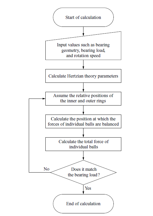
The calculation mainly consists of two steps. In the first step, the tool obtains the relative positions of the balls, inner ring, and outer ring where the force equilibrium is satisfied for the radial load, axial load, and moment load acting on the bearing, as well as the centrifugal force of the balls resulting from shaft rotation. As a result, the state quantities related to the contact between the individual balls and the inner and outer rings, such as reaction force, stress, and contact angle, can be acquired. This calculation is based on A. B. Jones’ theory(1). The calculation flow chart in the first step is shown in Fig. 4. In the second step, the tool calculates characteristics, such as bearing stiffness and vibration frequency, based on the calculation results in the first step.
3. Analysis output
3.1 Contact conditions between balls and inner and outer rings
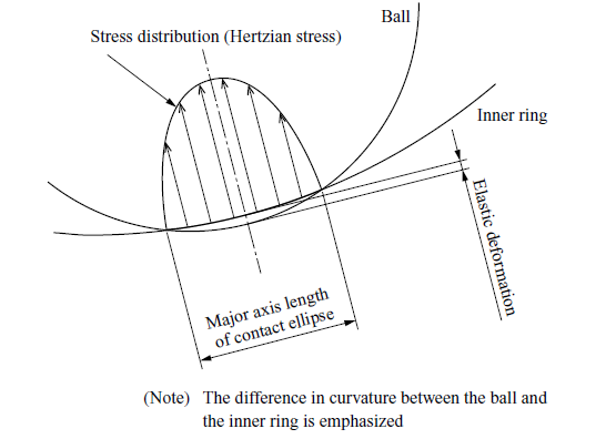
The groove curvature radii of the inner and outer rings are larger than the curvature radius of the balls by several percent. Therefore, the balls first have point contact with the inner and outer rings when their positions become close. Then, as the load increases, the balls support the load while undergoing elastic deformation, and the contact surface becomes elliptical. Because the area of this surface is small, stress becomes typically as high as around 2 GPa. The reaction force, stress, and elastic deformation at this time are important values that affect the lifetime and stiffness of bearings. The contact condition between a ball and the inner ring is shown in Fig. 5. Hertzian theory(2), (3), which handles the contact problem between two bodies considering elastic deformation, is used for this calculation.
3.2 PV value between balls and inner ring
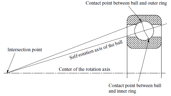
When the shaft rotates, the bearing balls revolve while self-rotating. It is known that the self-rotation axis of a ball has a specific orientation at this time(4). The state called outer ring control is shown in Fig. 6. In this state, the extension of the contact point between a ball and the outer ring intersects with the extension of the self-rotation axis of the ball on the centerline of the rotation axis. At this time, a kind of slipping called spin occurs in the contact surface between the ball and the inner ring. The spin slip on the inner ring side during outer ring control is shown in Fig. 7.
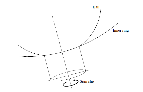
Hertzian stress shown in Fig. 5 acts between the spinning ball and the inner ring. Therefore, slip occurs with Hertzian stress acting on the ball and inner ring. Multiplying this stress by the slip speed results in the PV value. Their relationships are shown in Fig. 8. This PV value serves as an index for estimating the amount of heat generated by a bearing used at high speed and assessing the risk of bearing seizure when lubrication is insufficient.
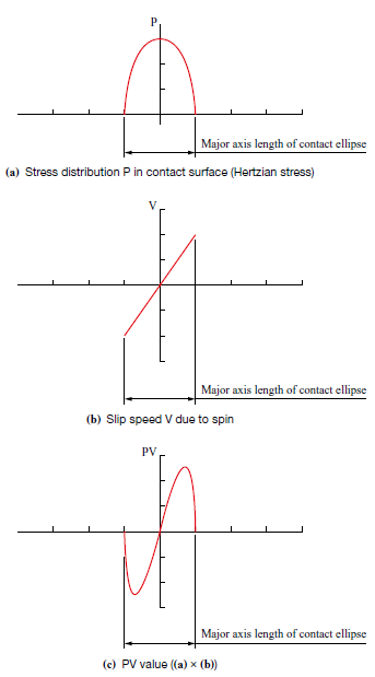
Note that, when an angular contact ball bearing rotates, the balls are pressed against the outer ring due to the centrifugal force, usually causing a larger friction on the outer ring side than on the inner ring side. As a result, the bearing usually rotates under outer ring control. However, under certain conditions, the inner ring may take control, causing a spin in the contact surface between the balls and the outer ring. This tool supports the calculation of both cases.
3.3 Bearing stiffness
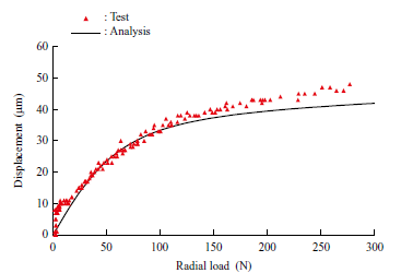
When a load acts on a bearing, the contact surface between the balls and the inner and outer rings support the load while undergoing elastic deformation. The relationship between this load and the amount of elastic deformation can be used to calculate bearing stiffness. Bearing stiffness is an important property that determines the natural frequency of the shaft. It is essential to accurately estimate bearing stiffness to avoid the resonant vibration of the shaft. Figure 9 shows a comparison example of the calculation result and actual measurement value of the radial stiffness of the angular contact ball bearing 7008A. As shown in this figure, the bearing load and the bearing displacement have a nonlinear relationship.
3.4 Calculation of frequencies
In ball bearings, when the shaft rotates at a certain speed, the balls self-rotate and revolve at speeds proportional to the shaft speed. The self-rotation and revolution speeds of the balls are determined based on the geometric relationship. Therefore, the frequencies of vibration and abnormal noise that occur when the inner, outer ring, or balls of a bearing are damaged can be obtained through calculation. Their calculation formulas(5) are shown in Table 2. When abnormal vibration occurs in a machine, comparing the vibration frequency with the calculated frequencies makes it possible to determine whether the abnormal vibration is caused by the bearing and, if so, where in the bearing is abnormal.
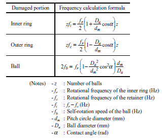
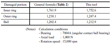
Although this frequency is affected by the contact angle of balls, the initial contact angle when the bearing is not rotating is often used for calculation. However, when the bearing is rotating at high speed under a small load, for example, the contact angle easily changes due to the centrifugal force acting on the balls. Accordingly, the vibration frequency also changes. This tool can perform calculations that take the impact of these changes into consideration. Differences resulting from these changes are small and ignoring them usually does not cause problems. However, this feature is useful, for example when it is necessary to distinguish the frequency of vibration caused by the bearing from the vibration generated from other components if these frequencies are close. Calculation examples of frequencies using this tool are shown in Table 3.
4. Conclusion
This paper introduced our in-house analysis tool to calculate the performance of ball bearings. Although we have continued to expand and improve the functions of this tool, increasing application cases, this tool can handle only a single bearing. On the other hand, there are also needs for estimating the performance of an entire shaft system that takes multiple bearings into consideration. Therefore, we are currently establishing a framework that enables analysis of both the entire shaft system and a single bearing by analyzing the entire shaft system with a commercially available tool and using its bearing load output as input to our in-house tool. We will continuously strive to develop and establish technologies that contribute to product development in the future.
REFERENCES
(1) A. B. Jones : A General Theory for Elastically Constrained Ball and Radial Roller Bearings Under Arbitrary Load and Speed Conditions, Journal of Basic Engineering, Vol. 82, No. 2, 1960, pp. 309-320
(2) H. Hertz : Über die Berührung fester elastischer Körper, Journal für die reine und angewandte Mathematik, Vol. 92, 1882, pp. 156-171
(3) J. Okamoto : Introduction to the Design and Calculation of Ball Bearings, Nikkan Kogyo Shimbun, Ltd., 2011 (in Japanese)
(4) Rolling Bearing Engineering Editorial Committee : Rolling Bearing Engineering, Yokendo Ltd., 1975 (in Japanese)
(5) M. Kobayashi, et al. : Issues involving the Noise and Vibration of Rolling Bearings -1-, Science of Machine, Vol. 20, No. 1, 1968, pp. 19-24 (in Japanese)