
Value Optimized Electric Compressor with Recuperation for Fuel Cell Systems
FILSINGER Dietmar
FILSINGER Dietmar : Ph.D., Technical Supervisor, Control Systems Engineering Department, Research & Engineering Division, Aero Engine, Space & Defense Business Area
The long-distance commercial vehicle sector is expected to adopt battery-electric fuel cell (FC) propulsion systems for their extended operating time and reduced downtime. In a three-year program the IHI Group and its partners Silver Atena GmbH and Technical University of Chemnitz developed an air supply system for FC utilizing a 25 kW electric high-speed motor, centrifugal compressor technology, and turbine recuperation as the most energy efficient technologies for such purposes. In this publicly funded value driven development project, disruptive technical solutions were engineered to optimize product cost and reduce weight through form-function mapping and simplification. The V-cycle and design-structure-matrix were rigorously applied to define verification and validation activities. The validation campaign confirmed the feasibility of the new electric air compressor architecture with recuperation for FC.
1. Introduction
Electric fuel cell (FC) propulsion is expected to gain traction in long-distance commercial vehicles due to extended operating time and minimized downtime(1), (2). In heavy-duty truck applications, total cost of ownership (TCO) is largely driven by fuel-related operating expenses (OPEX), which depend on system efficiency. While OPEX is critical, cutting capital costs (CAPEX) of FC systems (FCS) is also essential. Multiple studies, regardless of their geographic origin, aim for a threefold cost reduction by 2050(3)–(6).
In a proton exchange membrane (PEM) FCS, the electric driven compressor is key to boosting performance by increasing air pressure and flow, enhancing hydrogen oxidation and power density(7). For heavy-duty trucks, a turbocharger meets the power demands from high payloads, stabilizes temperature and pressure, and contributes to improved system durability(8). It also aids heat management and energy efficiency by turbine recuperation(9), leading to better fuel economy and lower operational costs(10).
An earlier study from the same research group explored how variations in FCS topology (battery capacity, FC module power, and number of modules) and air charging system technology affect TCO. System topology plays a critical role, so defining it based on mission requirements is crucial. Additionally, selecting the appropriate charging technology is key to optimize hydrogen consumption in heavy-duty truck battery-electric FC propulsion systems(11).
Considering this discourse, a new turbocharger, the AC+eR (Air Compressor + electric driven with Recuperation), has been developed for battery-electric FC propulsion in heavy-duty trucks. Funded by research grant 19/21046A, provided by the Federal Ministry for Economic Affairs and Climate Action on the basis of a decision of the German Bundestag, the AC+eR was designed to balance application requirements, performance, weight, reliability, and cost. Aimed at supporting FC performance and driving range in large commercial vehicles, the development focused on optimizing cost, reducing weight, and simplifying design through function integration. Therefore, this streamlined and disruptive design addresses sustainable environmental transportation challenges.
At the core of this development is the promise of green hydrogen — produced from renewable energy — as a clean fuel for FC vehicles. While limited infrastructure remains a major barrier, particularly the lack of refueling stations and distribution networks, green hydrogen is expected to play a key role in reducing transport CO₂ emissions. The AC+eR turbocharger reflects industry efforts to overcome these challenges, showing how advanced technology can help make hydrogen-powered transportation more viable despite current limitations.
This paper presents the design concept, and the related philosophy and methodology, aligned with product verification, and includes experimental validation results.
2. Design concept and architectural design
FC system components have often been optimized individually for high dynamics and peak load performance, aiming to replace combustion engines in powertrains.
IHI addressed this by developing an air supply system featuring a centrifugal compressor with foil air bearings and a recuperative turbine, which recovers exhaust energy to reduce energy consumption compared to conventional compressor systems(12), (13). This approach demonstrated both reliability and efficiency in the Daimler GLC F-Cell(14). However, improving cycle efficiency and ensuring cost-effective scalability remain critical. Consequently, any development needs to involve integral product optimization based on an understanding of the FC system and vehicle mission. Adapted component requirements reflect system needs evaluated from (numerical) system analysis and function integration as far as meaningful and possible, balanced with design flexibility. Emphasis should be placed on application-specific design with modularity, scalability, and flexibility, while optimizing costs across electrical, mechanical, and control sub-systems.
Efficient development of an optimized system that meets all goals and requirements demands a structured approach, ideally following the verification and validation model or V-cycle(15). System development begins with a thorough requirements analysis and architecture definition, based on a deep understanding of the system. This was generated via an intensive numerical system investigation already published(10). For a FC system in heavy-duty trucks, mission parameters such as operating time and load scenarios were analyzed to define component requirements. Similar to the approach by Rode et al.(16) on turbocharged dedicated hybrid combustion engines, simulations were used to study turbocharger behavior, loading conditions, and the effects of drive cycles. This informed the operating parameters — pressure, airflow, and mechanical boundary conditions like start-stop cycles — for the FC turbocharger. These insights guided the system architecture, component design, and enabled detailed planning for verification and validation at all levels, namely the component level, the sub-system level, and the turbocharger system level. Applying the V-cycle ensures that requirements are met and product quality is improved throughout the development process.
The system simulations indicate that the required pressure level can be achieved with a single-stage centrifugal compressor(10). Efficiency and power density improve further when combined with a turbine for exhaust energy recuperation, as supported by internal studies(17) and literature(7), (8), (18)–(21). Building on these findings and IHI’s experience with electrified turbomachinery(13), (17), (22), (23), the selected solution is an electrically driven centrifugal compressor with turbine recuperation. A low specific speed compressor and a mixed-flow turbine are mounted on a single shaft, driven by a two-pole permanent magnet synchronous machine (PMSM). This paper focuses on the rotating machinery; power electronics are not covered.
To achieve significant product cost reduction, existing air charging system architectures were analyzed with a focus on design simplification and function integration. Leveraging experience in turbocharger design(24), a rigorous design-to-cost approach was applied, following methods similar to those in Reference (25). Using form-function mapping, key functions were broken down and consolidated into as few components as possible. Major cost drivers in manufacturing and assembly were identified, and a balanced, multi-objective design strategy considering these aspects of industrial production was applied throughout all design stages(26).
Function integration offers clear benefits — greater compactness, fewer parts, lower cost, and weight savings. However, it can reduce flexibility, as designs may become unsuitable for applications that do not require all integrated functions. Function integration also poses challenges for verification and validation. Verification, based on theory or simulations, occurs early, while validation through hardware testing can obviously only be scheduled in later development stages. Strong numerical predictability is essential to achieve “first time right” designs, supported by early-stage reviews based on design experience and analysis. Therefore, in technology decision-making, (numerical) predictability and model accuracy must be considered.
This often favors proven, single-function components due to their simpler, more predictable behavior. Multi-functional components introduce complexity and uncertainty in both prediction and test result interpretation. However, with advanced multi-physics models and their appropriate numerical depth and interdisciplinary expertise, reliable validation of integrated components is achievable.
Based on this approach, multiple concepts with varying levels of simplification and function integration were evaluated, balancing cost reduction with technical risk. The concepts were evaluated in relative terms. The assessment employed weighted criteria for function, technical risk, and cost. A sensitivity analysis highlighted the trade-off between cost and risk, showing that higher costs can reduce technical risk. This allowed identification of backup solutions. As the study prioritized cost to improve the market potential of FC propulsion systems, the most simplified concept received the highest rating and was selected for implementation.
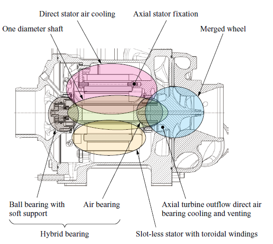
A cross section of the elaborated design of the electrically driven centrifugal air compressor with turbine recuperation is shown in Fig. 1. As described earlier, the rotor is driven by a PMSM. The outstanding features are:
- System wheel/merged wheel,
- Hybrid bearing system with one-diameter shaft,
- Stator with direct gas cooling,
- Slot-less stator with toroidal windings.
The following outlines the four essential innovative ideas of this novel turbocharger architecture.
2.1 System wheel/merged wheel
In an electric turbocharger for FC, maximum compressor outlet temperature depends on pressure ratio. At a 2.5 pressure ratio and > 80% efficiency, outlet temperatures reach around 125°C. The turbine, fed by PEM FC exhaust, operates at 70 to 90°C — much lower than in combustion engines. This allows the same material to be used for both turbine and compressor stages. Consequently, the form-function mapping approach suggests the integration of the compressor and turbine functions into one single merged wheel, allowing direct torque transfer in a back-to-back configuration. This reduces mechanical stress on the shaft and interfaces, cuts component count (e.g., seals, fasteners), and improves heat management. The turbine placed between the compressor and electric motor acts as a thermal shield, reducing motor cooling demand. Heat flow analysis shows slight cooling of the compressor outlet and mild heating of the turbine — enhancing overall efficiency, though the effect is limited due to the small heat transfer area. During lower-load conditions, the effect reverses, but with an insignificant impact on system performance. Related temperature changes are always lower than possible measurement accuracy.
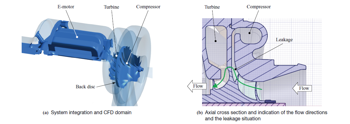
Figure 2 illustrates this integrated system wheel, featuring a mixed flow turbine (MFT) with its beneficial mass flow characteristics(27) and a compressor wheel with slightly non radial blades at the outlet and splitter blades to guide the flow efficiently. The shared back disc compromises MFT inflow by reducing the axial flow component but helps adjusting (reducing) the thrust load. While the turbine has a relatively large hub diameter, the axial outflow along the shaft avoids cross-sectional jumps and associated outlet losses — unlike conventional turbine wheels positioned at the rotor’s end.
with two functions: compression and recuperation
One issue that needs to be treated in the back-to-back wheel design is managing the small gap between the compressor and the turbine, which leads to leakage — mainly from the higher-pressure compressor to the turbine. Leakage varies with operating conditions and local pressure across the gap. However, this flow is not entirely wasted, as it still contributes to turbine power. Further details are discussed later in the paper.
2.2 Hybrid bearing system
FC are highly sensitive to contamination, making oil-free bearings — like air foil or grooved types — the preferred choice for FC compressors. Their reliable design requires outstanding engineering know how(28), (29) and their production needs very accurate manufacturing and assembly processes, leading to high costs. Magnetic bearings, which were also briefly investigated, do not offer any cost advantage either. The merged wheel design, however, frees one shaft end, allowing for a smaller shaft diameter without compromising rotor rigidity. This enables insertion of a pre-balanced rotor assembly from one side — ideal for mass production — and makes it possible to use life-time grease-lubricated high-speed angular contact ball bearings, which are significantly cheaper, since the small diameter allows adhering to state-of-the-art limit values of the Hertzian contact stress in the ball bearing’s raceways. A second, smaller bearing and an axial spring provide axial preload, maintaining ball contact. This setup can replace a radial air bearing and even serve as a thrust bearing, especially when combined with the merged wheel’s inherent thrust load adjustment. Reducing thrust loads also minimizes bearing friction and simplifies sizing.
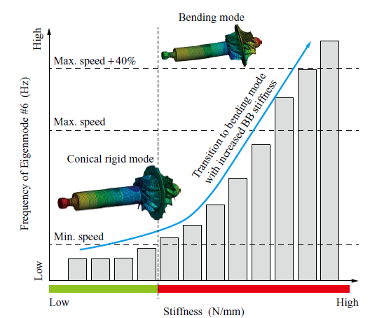
The hybrid bearing system — combining a stiff ball bearing with a softer air bearing — was thoroughly analyzed due to its engineering complexity. A key requirement was ensuring rotor eigenfrequencies remain safely above the maximum operating speed. To define a viable design space, a design-of-experiment-based automized parametric study was conducted, varying factors such as bearing distance, bearing width, magnet diameter and length (magnet surface defines the achievable electric motor torque), amor ring length, diameter, and thickness, as well as overhang of the merged wheel to name some of the most important ones. While this initial “free-free” modal analysis established baseline rotor dynamics, it was essential to include rotor-bearing interaction(30) through damped modal analysis. This revealed that overly stiff ball bearing support could shift a conical mode into the operating range and turn it into a more critical bending mode. As a result, optimal axial and radial stiffness values were defined to keep resonances out of the operating range, enabling reliable hybrid bearing operation. The final setup uses a small-diameter double-row ball bearing at the free shaft end to manage both radial and axial loads, and an air bearing installed next to the turbine outlet, with the turbine exhaust providing cooling and venting of the bearing. The air bearing is placed on the amor ring diameter for simpler shaft geometry, reducing part count, weight, and inertia — beneficial for performance and air bearing longevity, especially during start-stop cycles. Figure 3 shows how the bending mode’s (mode #6) frequency shifts with bearing stiffness. The border between the green and red bars highlight the safe stiffness threshold to avoid resonance.
2.3 Stator with direct gas cooling
High-speed electric motors are usually cooled indirectly, with liquid coolant circulating around the stator housing. Heat transfers from the stator through potting compound to the coolant. Since the potting compound adds significant cost, direct stator cooling is an attractive alternative for reducing cost and weight. Therefore, active direct gas cooling of the stator using turbine outlet flow was explored due to its benefits. The turbine exhaust, originally 70 to 95°C, cools during expansion, providing a suitably cold airflow ideal for motor cooling.
Automated numerical studies showed that turbine outlet flow can fully replace conventional water cooling for the stator across all operating conditions. Detailed design optimization focused on maximizing heat extraction by adjusting flow velocity, channel geometry, and pressure loss. This multidisciplinary approach also accounted for eddy current losses in the motor housing walls(31). The final design is simple, light, and cost-effective — eliminating water cooling channels and resin potting, replaced by simpler wire impregnation and insulation.
A parallel study examined turbine efficiency and found that using conventional water cooling with the hybrid bearing and merged wheel design required radial turbine outflow — negatively impacting axial space, rotor dynamics, and efficiency due to flow restrictions. This supported the choice of direct gas cooling via the axial turbine outlet.
Though this approach must manage humid exhaust from the FC (deionized water), it reduces development complexity and prevents contamination from grease-lubricated bearings. Additionally, using turbine outlet flow for both stator cooling and bearing venting eliminates the need for extra piping, allowing all compressed air to go directly to the FC stack.
2.4 Slot-less stator with toroidal windings
The newly developed electric motor features a slot-less stator with a ring-shaped iron yoke divided circumferentially to allow automated winding. Unlike more conventional stators, it has no teeth or slots, and the windings are arranged in the opposite direction to conventional distributed windings. This reduces winding head size, enabling a shorter axial length and allowing for axial cooling flow through the motor.
For geometric reasons and due to the orientation of the magnetic flux this stator design leads to a large magnetic air gap between the rotor and the iron core, requiring more current for a given torque but significantly reducing rotor losses(32). This lower heat generation in the rotor permits the use of cheaper NdFeB magnets instead of SmCo magnets and improves rotor temperature stability — beneficial for rotor dynamics and thermal expansion control. Smaller thermal shifts also enable tighter wheel gaps despite the distant axial shaft fix point. The slot-less stator helps minimize noise and vibration by avoiding magnetic field irregularities.
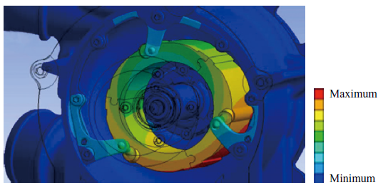
A novel axial clamping system secures the stator using three guide rods and a clamping ring, simplifying assembly and ensuring robustness. The rods provide guiding, and the screwed ring provides pretension against the supporting surfaces of the housing. Static and dynamic simulations confirmed its durability and acceptable vibration behavior. Figure 4 illustrates the concept and exemplarily simulated twisting mode amplitudes.
Overall, the motor’s efficiency is expected to match that of conventional designs, despite a larger rotor-stator gap. Most losses occur in the stator, which is easier to cool. However, eddy current losses in the housing must also be managed. This required a compromise in setting the gap between the stator and motor housing — smaller gaps improve cooling, while larger gaps reduce eddy current losses.
Developing complex systems demands rigorous verification and validation along the V-cycle to steadily reduce risk over time. This requires a systematic approach, strong verification capabilities, and engineering creativity to focus on the most critical investigations. The following chapter outlines the applied process.
3. Component, sub-system, and system verification & validation
Effective, lean product development requires early and meaningful verification and validation to minimize design changes and project delays. As the design matures, investigations grow in depth and detail, becoming more relevant. For example, thermal management investigations may begin with one-dimensional conceptual analyses, progress to two-dimensional evaluations, and only reach their highest accuracy once the architectural design is sufficiently defined to allow for three-dimensional analysis. Engineering judgment is key to selecting simple yet impactful assessments, with priority given to the highest technical risks and novel features. If uncertainties remain, early validation should be planned. A tool to help determine the relevance and scope of verification and validation activities is the design structure matrix (DSM)(33).
The DSM visualizes interactions between system components across disciplines — structural integrity (both static and dynamic), thermal, aerodynamic, and electromagnetic — helping identify which parts can be analyzed independently on component level and which require sub-system or full-system context. Figure 5 provides an overview of these system levels.
The DSM helps define system boundaries and the necessary detail level for numerical or physical models used in simulations or experimental studies across the different disciplines by classifying interaction types (e.g., thermal) and evaluating their strength and impact on the system’s primary function.
For brevity, the full process is not detailed here, but key DSM outcomes along the V-cycle included: the need for early aerodynamic validation of the merged wheel, critical for system performance; experimental validation of the hybrid bearing with the one-diameter shaft, central to the design; and system-level thermal analysis accounting for all physical effects — thermo-aerodynamics of compressor and turbine, coolant flow, friction, electromagnetic losses, and structural heat conduction.
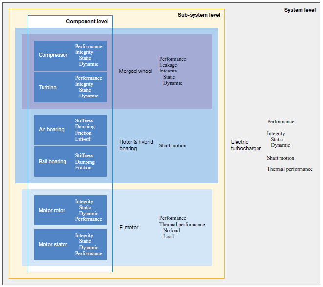
State-of-the-art verification(24) was successfully performed at individual component, sub-system, and system levels — from basic strength checks (e.g., pressure-loaded housings, circumferential load of rotating wheels) to complex dynamic analyses of the rotor sub-system and vibration assessments of the full housing assembly with stator under internal and external excitations (see Fig. 4). Containment was also verified through advanced simulation.
The following section summarizes key verification and sub-system validation activities for merged wheel aerodynamics, rotor dynamics, and thermal management.
3.1 Merged wheel
3.1.1 Aerodynamic design
Paramount is the aerodynamic performance for any turbocharger. Verified through proven three-dimensional CFD methods, both compressor and turbine stages were evaluated. Blade geometries were created within axial length and mass constraints, defined via the design space investigations explained above. The wheel hub was shaped for performance optimal integration with the one-diameter shaft. Simulations confirmed state-of-the-art efficiency meeting the application requirements(10). For the heavy-duty truck mission, higher load operating conditions with a compressor pressure ratio above 2.0 were focused during automated parameterized multi-condition optimization.
A small but efficiency-reducing leakage between compressor outlet and turbine inlet must be minimized. This requires understanding and influencing local pressure conditions along the leakage path through targeted design features. The pressure difference between the compressor outlet and turbine inlet is dominated by the pressure drop in the stack, but also affected by piping losses and turbine exit back pressure. The radial gap location and degree of reaction of compressor and turbine allow for some leakage control. Design variants are evaluated using combined three-dimensional CFD simulations of compressor and turbine stages. The general leakage situation and the CFD domain of the complete model is already illustrated in Fig. 2.
To better understand the complex flow — affected by swirl at the compressor outlet and turbine inlet(34), (35) — basic geometry variations were studied. Evidently leakage is mainly driven by radial gap height but can also be reduced by features like steps or labyrinths; for instance, a simple compressor-side step cut leakage by 50%, down to approximately 3% of total compressor inlet flow. While some leakage is recovered in the turbine, making its impact on compression power negligible at high loads, it must still be accounted for when matching air supply to FC demand. It is worth mentioning that any design feature must accommodate both axial and radial movement without allowing contact between rotating parts and the housing.
While modern CFD provides reliable results, experimental validation was essential due to the novelty of the merged wheel concept.
3.1.2 Aerodynamic testing
Due to the complex flow, early experimental validation of the merged wheel through sub-system testing was needed alongside isolated compressor and turbine map measurements. Engineering creativity led to sub-system testing with a turbine driven assembly based on standard automotive turbocharger (Fig. 6) by replacing its original compressor stage with the FC compressor, the FC turbine, or the merged wheel assembly, respectively. Performance maps were obtained using standard measurement methods(24).
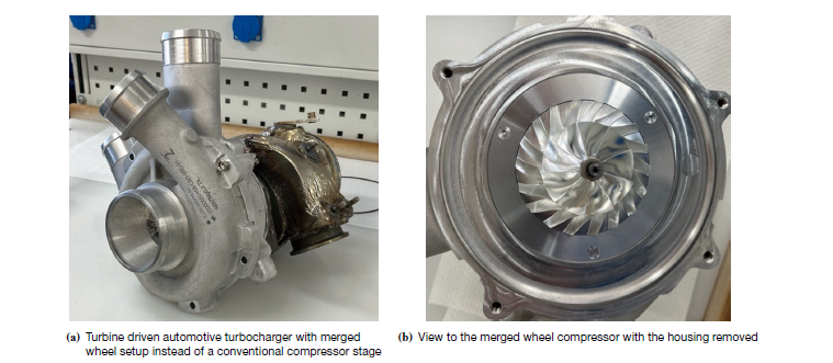
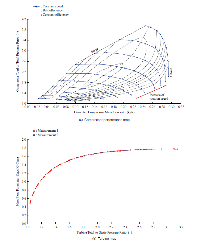
Figure 7 presents the measured and corrected performance maps for the compressor and turbine in the component setup. Results aligned with predictions, showing competitive efficiency for the nozzle-less, fixed-geometry designs. Efficiency could be further improved with a vaned diffuser, depending on map width needs.
As simulations showed that leakage in the merged wheel can be influenced by local geometry, various design variations were tested in sub-system experiments to explore potential improvements. Gap design also considered shaft movement during operation, with current results suggesting further gap reduction is achievable.
In the sub-system test, a radial turbine outlet was required due to design constraints. For relevant operation, leakage reached up to 7% of compressor inlet flow but had minimal impact on system power. Leakage increases near surge and decreases at higher compressor pressure ratios. Its behavior depends on pressure balance defined by operating conditions, aerodynamics, and local geometric design. At high mass flow and pressure ratios, leakage may reverse — undesirable but acceptable for this initial design. The risk of turbine-to-compressor leakage and potential stack contamination is considered low for the intended operation. Measures to modify the leakage flow, if needed, are available.
Numerical and experimental results confirmed the performance of the innovative AC+eR design. In addition to performance, the high-speed rotor requires detailed evaluation.
3.2 Hybrid bearing
3.2.1 Design of hybrid bearing
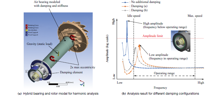
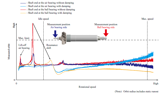
The rotor and bearing design was firstly evaluated using harmonic analysis by simulation with state-of-the-art finite element methods. Air bearing properties were based on prior tests(29), while ball bearing support’s stiffness and damping were derived from actual geometry and literature data for EPDM elastomers(36). Elastomer rings were added for damping, support stiffness target values were defined as explained in Fig. 3. Unbalance was set at twice the maximum allowable value. Results in Fig. 8 show that without damping, deflections are high but occur below idle speed, meeting design targets. Adding damping leads to slightly shifting the resonance into the operating range, but expected amplitudes remain safe. Figure 8 also shows two damping scenarios (a) and (b) that reflect the change of damping behavior under aged conditions(37).
3.2.2 Shaft motion testing
Based on the theoretical understanding, different tests from component to sub-system tests were designed to validate the behavior of the high-speed rotor. Component tests focused on the novel ball bearing support, confirming stiffness and durability. A shaker setup with dummy masses was used to match the eigenfrequencies of the sub-system setup with the eigenfrequencies of the full bearing rotor assembly. The same setup was used for durability and aging studies of the elastomer damping element under FC exhaust conditions. While not detailed here, results are available in Reference (37).
Air bearing tests focused on friction, as the design is already validated(38), and bearing loads are low due to the lightweight one-diameter rotor.
The bearing system was tested as a sub-system in a turbine-driven rotor dynamic dummy replicating the FC turbocharger’s key properties (e.g., eigenfrequencies, center of gravity, inertia). These tests were done with varying damping levels, including none, as numerical modeling of real structural damping remains challenging(36). Therefore, the most reliable comparison between analysis and experiment is the case without damping. Unbalance was adjusted using added weights to the rotor. Figure 9 shows shaft motion results under maximum allowable unbalance, with measured orbits at both shaft ends across speeds.
Shaft motion measurements confirm that the undamped low-speed frequency prediction is sufficiently accurate, with an 8% deviation. The results also show the damping effect. The resonance frequency shifts due to stiffening and a clear reduction in orbit amplitudes can be observed. Without damping, the highest amplitudes occur near the ball bearing. With damping, amplitudes at both shaft ends drop to safe levels, though the ball bearing side still sees the highest in-operation amplitude. Finite element analysis (FEA) confirms the ball bearing support can withstand these loads long-term.
The measurement also shows air bearing lift-off occurring well below the defined idle speed. This is an intended outcome, aided by the reduced weight of the merged wheel rotor assembly.
These results confirmed the rotor unbalance limits and damping setup. This successful sub-system validation greatly strengthened confidence in the design architecture of the FC turbocharger.
The third key investigation is on the thermal management of the turbocharger.
3.3 Thermal management
A single housing integrates the compact electric motor and thermal turbomachinery. Since the design uses turbine exhaust to cool the motor and bearings — combined with a new slot-less stator with toroidal windings — detailed simulations were carried out before hardware testing.
Initial one-dimensional studies during motor layout indicated that direct exhaust gas cooling can be designed to be as effective as conventional liquid cooling. A key advantage is the turbine’s placement, which shields the motor core from the compressor’s hot section.
The DSM highlighted the need for detailed multi-physics analysis. A weakly coupled three-dimensional simulation approach was chosen, combining electromagnetic analysis with CFD and thermal modeling by FEM. A three-dimensional CFD steady-state model featuring the compressor and turbine passage as well as the motor cavity was created (compare to Fig. 2), and boundary conditions were extracted for the thermal model. Media of the turbine flow was saturated humid air to represent the FC exhaust. Phase change was not modeled, introducing some uncertainty in local temperatures and underestimating heat transfer — making the results conservative. In the thermal FEA, convection was represented by local heat transfer coefficients and temperatures.
The three-dimensional electromagnetic analysis confirmed key benefits of the slot-less design: low cogging torque, minimal torque ripple, reduced air gap harmonics, and low rotor losses. However, higher stator joule losses require a high copper fill factor and improved inverter performance. Due to winding proximity, the housing is subject to eddy current losses(39) not typical in conventional machines, requiring close monitoring. Various winding head models were tested to assess these effects. More details on the methodology are available in Reference (31). Figure 10 illustrates heat transfer coefficients and the resulting three-dimensional temperature distribution at 120,000 rpm and 25 kW.
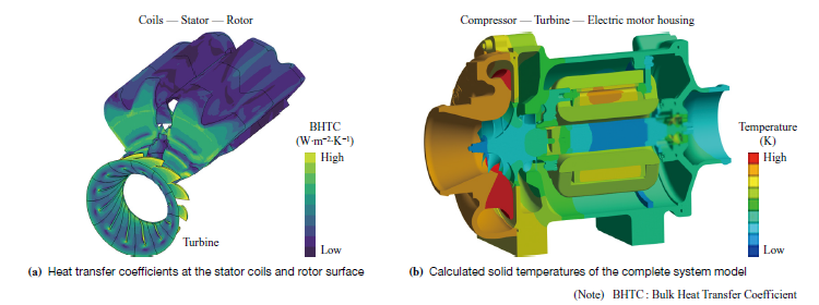
All component temperatures remain well below material limits. As expected, the compressor stage is hottest, caused by maximum gas outlet temperatures over 150°C. Heat conducts from the compressor to the adjacent turbine housing, but the much cooler turbine gas protects the motor-side housing, keeping the walls only slightly above turbine inlet temperature. The thermal model also includes speed-dependent bearing friction and windage losses from the motor rotor and motor stator gap. Crucially, reliable temperature prediction depends on the losses of the electric motor accurately calculated by three-dimensional electromagnetic analysis.
The system benefits from the turbine exhaust’s low cooling temperature (< 50°C at rated power), keeping simulated stator and rotor temperatures well within safe limits. Rotor temperatures are particularly low, supporting a robust design. Bearing friction causes local temperature rises, especially at the ball bearing races, but all remain below allowable thresholds. However, due to modeling assumptions and uncertainties, system validation remains essential.
Cooling variability — due to changes in inlet pressure, mass flow, and temperature along the FC compressor’s operating line — required analysis of low-load conditions. Even at low flow, predicted temperatures remain safely low.
Confident from positive verification and sub-system validation results, the full system was built and tested.
3.4 System testing
System testing on an A-sample verified key features: motor electromagnetic performance, thermodynamics, thermal behavior, and rotor stability. Limited durability cycles, based on application experience and simulations(10), were also successful but are not detailed here. Figure 11 shows the novel FC turbocharger used during the system testing.
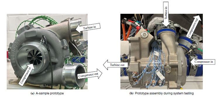
Thermodynamic test results from component and sub-system levels were confirmed at the full system stage. Shaft motion tests matched rotor dynamic sub-system findings, showing effective damping of low-speed resonance and no critical rotor deflections across speeds. All earlier conclusions on these key features were also validated in the system tests.
As predicted by CFD, leakage decreases in the full system versus sub-system tests due to a more favorable axial turbine outlet affecting local pressure distribution. Consequently, the crossover between positive and negative leakage occurs at lower pressure ratios.
The system reached maximum speed within inverter power limits, confirming motor and inverter efficiency. Detailed investigations to judge the motor efficiency and losses are underway. The inverter exceeded 98% efficiency over a wide speed and voltage range. Turbocharger ramp-up was under one second to 90% maximum speed, surpassing standard requirements.
Figure 12 shows example temperature readings to illustrate the thermal behavior of the electrified turbomachinery. It compares two operating points (A and B) on the compressor map, where the compressor pressure ratio is reduced but mass flow — and thus FC power output — remains constant. The bar graphs display the relative steady-state temperatures, referenced to the compressor outlet temperature at high pressure ratio operating point A, as well as changes in speed and pressure ratio.
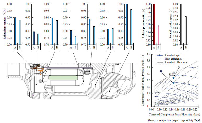
As predicted by simulations, the highest system temperature for (A) and (B) remains the compressor outlet temperature, which drops with reduced pressure ratio, while turbine inlet temperature stays constant, set by FC operation. The turbine outlet (cooling gas, not shown in Fig. 12) temperature rises as turbine pressure ratio decreases. The FCS behavior is simulated in the test setup by adjusting a pressure loss between the compressor outlet and the turbine inlet. In the given test setup, a Zeta value according to Reference (38) between 0.6 and 0.8 is realized. Whereas Zeta is defined as the ratio of the pressure difference between the turbine inlet and ambient to that between the FC stack inlet and ambient. High Zeta values are beneficial, since this gives high recuperation potential. Despite higher cooling gas temperature for (B), metal temperatures drop due to only 79% electric power demand compared to (A) and reduced rotor speed (< 94%), which lowers bearing friction. Stator winding temperatures are cooler at the inlet than the outlet due to better cooling flow. The outlet temperature of the cooling gas is also reduced for the lower pressure ratio operation (B), but only slightly because of its increased entry temperature. Temperature variations around the stator circumference (not shown here) reflect uneven flow and local wiring blockages, indicating room for design improvements. The temperature at the stator iron core could not be measured, but based on calibrating simulation with stator surface temperatures the expected core temperatures did not limit the operation.
The investigation clearly shows that thermal management is most critical near the compressor surge line, where pressure ratio is highest and flow lowest (see Fig. 12). Thermal measurements across the compressor map confirmed this and demonstrated that, within the intended operating range — defined by pressure ratio, mass flow, electric motor power, and rotational speed — all component temperatures stayed within allowable limits.
Thermal evaluation remains an area for further optimization due to the complex flow. Both bearings stayed within temperature limits, but improved direct cooling of the ball bearing may be beneficial. Future work may refine internal cooling flow paths along the air bearing, the stator, and the ball bearing and enhance three-dimensional models using steady-state and transient measurement data. A key factor — though not covered here — is better quantification of electromagnetic losses.
Substantial testing has been performed, including turbine droplet resistance studies(40), (41), and the validation experiments have confirmed the design concept. Consequent function integration and design simplification significantly reduced weight by more than 30% and component costs by more than 50% compared to a reference product. Fewer parts and a focus on manufacturability and assembly helped achieve competitive product costs.
4. Conclusion
Over the three-year program, presented in this paper, a novel air supply system for mobile FC systems was developed, using centrifugal compression and turbine recuperation for high energy efficiency. Figure 13 gives the synopsis of the AC+eR and outlines the key characteristics. The 25 kW continuous output power of the electric motor in combination with turbine recuperation and the maximum rotational speed of the electrified turbocharger is sufficient for serving FCS outputs over 150 kW. The turbocharger, excluding the inverter, weighs 9.22 kg, achieving a specific power of 2.71 kW/kg.
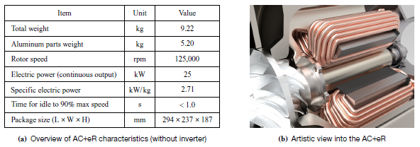
For conventional designs as well as for this presented design study, weight reduction correlates with cost savings, but it also supports resource conservation and lowers the product carbon footprint (PCF). The conservation of any resources, not only the scarce and crucial ones, must be a primary driver in all new developments. Carbon footprint, determined through life cycle analysis, needs to be considered a key metric alongside cost in evaluating products serving the energy transition. Most of the AC+eR’s system weight comes from aluminum housings with aluminum being the main contributor to the turbocharger’s PCF — approximately 17 kgCO₂e/kg for primary aluminum(42). For the total electrified turbocharger (excluding the inverter), the CO₂ equivalent was estimated to be around 12 kgCO₂e/kg, with the motor rotor assembly being the largest specific contributor. These values are based on an internal investigation into PCF for electrified turbochargers, following ISO14040 standards, and make clear that a 30% weight reduction substantially lowers the PCF.
This publicly funded value driven development project focused on cost and weight reduction through highly simplified, functionally integrated designs. Disruptive technical solutions were engineered, verified, and preliminarily validated. By mapping form to function and targeting manufacturing and assembly cost drivers, projected product costs were significantly lowered. The V-cycle was strictly followed, using the design structure matrix to guide effective verification and validation efforts.
The electric air compressor for FC with turbine recuperation comprises four key features:
- the merged wheel design,
- the hybrid bearing system,
- the stator with direct active gas cooling,
- the slot-less stator with toroidal windings.
(1) and (2) enable a manufacturing- and assembly-friendly one-diameter rotor and efficient integration of the permanent magnet into a protective sleeve. The rotor can be fully pre-assembled before installation into the stator. A reduced thrust load allows a small-diameter ball bearing to handle both axial and radial loads. The axial fix point, defined by a ball bearing with tight tolerances, helps minimize tip gaps. Simple torque-controlled clamping is sufficient due to reduced interface loads, enabling a compact wheel design with a smaller hub. The turbine benefits from a smooth outflow without a sudden increase of the surface area at the hub and acts as a thermal barrier to the hot compressor, aiding thermal management. Using turbine outlet flow to cool and vent the air bearing eliminates the need for additional compressed air, improving system efficiency and avoiding FC contamination from ball bearing lubrication. The only trade-off is managing leakage between compressor and turbine — though any flow to the turbine still contributes to recuperation.
(3) and (4) are also the result from rigorous system function analysis. The coil winding direction enables direct stator cooling using turbine outflow, simplifying the design. The toroidal, slot-less stator allows axial fixation and reduces axial length. Its electromagnetic properties promise reduced rotor losses with equally reduced challenges to treat thermal effects in the rotor. Eddy current losses in the housing were balanced with a housing design for optimized cooling flow.
This development clearly benefits from high function integration, resulting in greater compactness, fewer parts, and ultimately better cost efficiency and weight savings. However, function integration also reduces flexibility for broader application and may require adapted operation strategies. For example, in this case, a specific cooldown operational procedure is needed, as motor cooling relies on turbine outlet flow, which depends on the FC system’s operation.
The validation campaign confirmed the feasibility of this novel design concept of an electrified FC air compressor with recuperation. The performance targets serving a 150 kW FCS were fulfilled. The temperature limits for full load, but also part load operations were kept.
Further improvements are possible — such as optimizing cooling flow, reducing eddy current losses in stator and housing, exploring alternative ball bearings, vibration absorbers, axial load balancing via magnetic forces, flexible housing fixation with V-clamps, and welded armor ring solutions. These refinements can be targeted in a next development phase of this unique air supply concept.
- — Acknowledgments —
-
The author is grateful for the financial support under the research grant 19/21046A provided by the Federal Ministry for Economic Affairs and Climate Action on the basis of a decision by the German Bundestag.
The named author is responsible for the content of this paper but is in debt to an outstanding team that in its best sense “delivered” — first and foremost Martin Rode and Sasa Slavic, but also Roberto DeSantis, Dr. Dario DiModica, Dr. Lee Gibson, Dr. Torsten Gramsch, Kathrin Holz, Georgios Iosifidis, Lorenz Jaennike, Daniel Just, Kai-Uwe Krause, Sebastian Kunze, Dr. Thomas Leonard, Rohit Pawar, Tamas Pinter, Dr. Johannes Ratz, Dr. Reimar Schaal, Mario Tränkner. This needs to be even more valued since along the project execution a company transformation in a most impacting form was mastered.
The author would like to express his gratitude to the project partners at Technical University of Chemnitz and Silver Atena GmbH for their collaborative spirit: “This is how partnerships pay back”.
REFERENCES
(1) M. Sens, C. Danzer, C. von Essen, M. Brauer, R. Wascheck, et al. : Hydrogen Powertrains in Competition to Fossil Fuel based Internal Combustion Engines and Battery Electric Powertrains, Proceedings of the 42nd International Vienna Motor Symposium, 2021
(2) M. Thewes, D. van der Put, M. Walters, D. Lückmann, A. Schloßhauer, et al. : Aging of Fuel Cell Systems for Heavy Duty Trucks – Mitigation Strategies and How to Validate Efficiently During the Development, Proceedings of the 45th International Vienna Motor Symposium, 2024
(3) J. Marcinkoski, R. Vijayagopal, J. Adams, B. James, J. Kopasz and R. Ahluwalia : Hydrogen Class 8 Long Haul Truck Targets, DOE Advanced Truck Technologies, 2019
(4) New Energy and Industrial Technology Development Organization (NEDO) : FCV-HDV Fuel Cell Technology Roadmap, Hydrogen and Fuel Cell Strategy Council, 2023
(5) China Society of Automotive Engineers : Energy-Saving and New Energy Vehicle Technology Roadmap 2.0, China Society of Automotive Engineers, 2020
(6) Z. Mu, F. Zhao, F. Bai, Z. Liu and H. Hao : Evaluating Fuel Cell vs. Battery Electric Trucks: Economic Perspectives in Alignment with China’s Carbon Neutrality Target, Sustainability, Vol. 16, 2427, doi:10.3390/su16062427, 2024
(7) A. Kerviel, A. Pesyridis, A. Mohammed and D. Chalet : An Evaluation of Turbocharging and Supercharging Options for High-Efficiency Fuel Cell Electric Vehicles, Applied Sciences, Vol. 8, 2474, doi:10.3390/app8122474, 2018
(8) F. Uhrig, M. Schinnerl, P. Haluska, P. Kurzweil and T. von Unwerth : Comparative Study of Different Air Supply Systems for Automotive Fuel Cell Applications, SAE International Journal of Alternative Powertrains, 2019, pp. 29-40
(9) C. Doppler, B. Lechner, A. Romero Mancebo, D. Schlueter, R. Schruth, C. Ahamer, B. Schobesberger, E. Wahlmüller and M. Zarhuber : Operation of Fuel Cell Systems in Challenging Thermal Environmental Conditions, Proceedings of the 45th International Vienna Motor Symposium, 2024
(10) P. Rathke, D. V. Di Modica, S. K. Fink, D. Filsinger, R. Burgmair and T. von Unwerth : Model Based Investigation on Drive Train Performance of a Heavy-Duty Fuel Cell Truck Focussing on the Fuel Cell Air Delivery System, FC3 Fuel Cell Conference, 2024
(11) P. Rathke, D. Filsinger, D. V. Di Modica, S. K. Fink, E. Pohl and T. von Unwerth : Investigation on Total Cost of Ownership for Fuel Cell Truck in Heavy Duty Long Haul Application and the Influence of Electric Turbocharger, International Journal of Hydrogen Energy, Vol. 193, 152352, doi:10.1016/j.ijhydene.2025.152352, 2025
(12) IHI Corporation : Striving to Realize a Sustainable Mobility Society, IHI Engineering Review, Vol. 54, No. 2, 2021
(13) K. Hayashi, S. Kaneda, N. Ikeya, Y. Daito and K. Kitamura : Development of Electric Turbocharger for Fuel Cell Systems to Contribute to the Realization of Carbon Neutrality, IHI Engineering Review, Vol. 56, No. 1, 2023
(14) C. Mohrdieck and S. Dehn : The Intelligent Fuel Cell Plug-in Hybrid Drive System of the Mercedes-Benz GLC F-Cell, MTZ worldwide, Vol. 80, 2019, pp. 30-37
(15) O. de Weck : Fundamentals of Systems Engineering: Systems Engineering Overview and Stakeholder Analysis, MIT Lecture Notes, MIT OpenCourseWare, 2015
(16) M. Rode, D. Filsinger, G. Iosifidis and L. Durbiano : Turbocharging for Combustion Engines in Hybrid Propulsion Systems, MTZ worldwide, Vol. 82, 2021, pp. 16-23
(17) D. Filsinger, G. Kuwata and N. Ikeya : Tailored Centrifugal Turbomachinery for Electric Fuel Cell Turbocharger, International Journal of Rotating Machinery, doi:10.1155/2021/3972387, 2021
(18) S. Martinez-Boggio, D. Di Blasio, T. Fletcher, R. Burke, A. García and J. Monsalve-Serrano : Optimization of the air loop system in a hydrogen fuel cell for vehicle application, Energy Conversion and Management, Vol. 283, 116911, 2023
(19) W. Yu, X Sichuan and H. Ni : Air compressors for fuel cell vehicles: A systematic review, SAE International Journal of Alternative Powertrains, Vol. 4, 2015, pp. 115-122
(20) N. Ahsan, M. Mehmood and A. A. Zaidi : Fuel Cell designing with optimal high speed air compressor, Energy and Thermofluids Engineering, Vol. 1, 2021, pp. 29-38
(21) M. L. Smith, A. Fritot, D. Di Blasio, R. Burke and T. Fletcher : Matching and Control Optimization of Variable Geometry Turbochargers with Hydrogen FCEVs, doi:10.20944/preprints202503.0334.v1, 2025
(22) M. Rode, T. Suzuki, G. Iosifidis and T. Scheuermann : Electric Turbocharger Concept for Highly Efficient Internal Combustion Engines, MTZ worldwide, Vol. 80, 2019, pp. 120-125
(23) M. Rode, T. Suzuki, G. Iosifidis, L. Durbiano, D. Filsinger, et al. : Boosting the Future with IHI: a comparative evaluation of state-of-the-art TGDI turbo concepts, Proceedings of 24th Supercharging Conference, 2019
(24) D. Filsinger, G. Iosifidis, L. Durbiano, C. Kirschner and J. Ehrhard : On Advanced Turbocharger Technology and Development, IHI Engineering Review, Vol. 56, No. 1, 2023
(25) P. Wang and C. Lusardi : Leveraging ICE Air System Technology for Fuel Cell System Cost Reduction, DoE Hydrogen Program, 2023 Annual Merit Review and Peer Evaluation Meeting, 2023
(26) C. Favi, M. Germani and M. Mandolini : Design for Manufacturing and Assembly vs. Design to Cost: toward a multi-objective approach for decision-making strategies during conceptual design of complex products, 26th CIRP Design Conference, Procedia CIRP, Vol. 50, 2016, pp. 275-280
(27) B. Lüddecke, D. Filsinger and J. Ehrhard : On mixed flow turbines for automotive turbocharger applications, International Journal of Rotating Machinery, Volume 2012, 589720, doi:10.1155/2012/589720, 2012
(28) A. Furuno and N. Omori : Design and Performance Evaluation of Gas Foil Bearing for Turbo Blower, Japan Society of Mechanical Engineers, 2016
(29) S. Yoshinaga, S. Aoyama, K. Yamaguchi and T. Jikumaru : Elemental Technologies to Realize Electrification of High Speed Rotating Machinery, IHI Engineering Review, Vol. 54, No. 1, 2021
(30) W. Köhl, M. Kreschel and D. Filsinger : Modellabgleich eines Turboladerrotors in Schwimmbuchsenlagerung anhand gemessener Schwimmbuchsendrehzahlen, 11. Internationale Tagung Schwingungen in rotierenden Maschinen, 2015
(31) G. S. Arvithis, G. Iosifidis, R. DeSantis, M. Rode, R. Burgmair and A. I. Kalfas : Novel Modeling Methodology for Thermal Evaluation of an Electrically Assisted High-Speed Turbomachine, Engineering Proceedings, Vol. 90, Iss. 1, 48, doi:10.3390/engproc2025090048, 2025
(32) F. Xu : Investigation of High-Speed Permanent Magnet Motors with Toroidal Windings, PhD thesis, University of Sheffield, 2022
(33) C. Gorbea, T. Spielmannleitner, U. Lindemann and E. Fricke : Analysis of Hybrid Vehicle Architectures Using Multiple Domain Matrices, 10th The Internatinal Design Structure Matrix Conference, 2008
(34) T. Leonard, S. Spence, A. Starke and D. Filsinger : Numerical and Experimental Investigation of the Impact of Mixed Flow Turbine Inlet Cone Angle and Inlet Blade Angle, Journal of Turbomachinery, Vol. 141, Iss. 8, 081001, 2019
(35) L. Gibson, S. Spence, S. I. Kim, C. Stuart, M. Schwitzke, A. Starke and D. Filsinger : An Investigation into the Effect of Clearance Aspect Ratio on the Performance of a Variable Geometry Vaned Diffuser for Automotive Turbocharger Application, ASME Turbo Expo, GT2020-14905, 2020
(36) A. Bormann : Elastomerringe zur Schwingungs-beruhigung in der Rotordynamik — Theorie, Messungen und optimierte Auslegung, PhD thesis, Technical University of Berlin, 2005
(37) A. Gaitanidou, M. Tränkner, G. Iosifidis, R. DeSantis, T. Efstathiadis and A. I. Kalfas : Degradation of Elastomer Damping Component for High-Speed Bearings, Engineering Proceedings, Vol. 90, Iss. 1, 54, doi:10.3390/engproc2025090054, 2025
(38) D. Filsinger, J. Ehrhard, G. Kuwata and N. Ikeya : Electric turbocharger for Fuel Cells – IHI’s contribution to sustainable mobility, FC3 Fuel Cell Conference, 2022
(39) M. Adrian, L. Marian and K. Mariusz : Influence of an end-winding size on proximity losses in a high-speed PM synchronous motor, Selected Problems of Electrical Engineering and Electronics (WZEE), 2015
(40) G. Karakasis, S. Kunze, G. Iosifidis and A. Kalfas : Development of a Test Stand for Electric Fuel Cell Turbocharger Integrity Testing, Part-1 Setup, XXVII Biennial Symposium on Measuring Techniques in Turbomachinery Transonic and Supersonic Flow in Cascades and Turbomachines, 2024
(41) G. Karakasis, S. Kunze, G. Iosifidis and A. Kalfas : The Development of a Test Stand for Electric Fuel-Cell Turbocharger Integrity Testing — Part 2: Results, Engineering Proceedings, Vol. 90, Iss. 1, 30, doi:10.3390/engproc2025090030, 2025
(42) International Aluminum Institute (IAI) : Specifiers’ Guide to IAI’s Carbon Footprint Methodology, < https://international-aluminium.org/wp-content/uploads/2024/10/Good-Practice-Carbon-Footprint-October-2023.pdf >, 2023