Ultimate Limit State Evaluation for Overspeed Burst of Ti-6Al-4V Disk
KITAMURA Yuta, TSUNORI Mitsuyoshi, YAMADA Takehisa, USHIDA Hirohisa
KITAMURA Yuta : Doctor of Engineering, Manager, Computational & Mathematical Engineering Department, Technology Platform Center, Corporate Research & Development Division
TSUNORI Mitsuyoshi : Doctor of Engineering, General Manager, Administration Department, Corporate Research & Development Division
YAMADA Takehisa : Doctor of Engineering, General Manager, Materials & Structural Engineering Department, Technology Platform Center, Corporate Research & Development Division
KITAMURA Yoshiyuki : Manager, Engine Technology Department, Research & Engineering Division, Aero Engine, Space & Defense Business Area
USHIDA Hirohisa : Manager, Advanced Technology Department, Research & Engineering Division, Aero Engine, Space & Defense Business Area
In aero engines, it is expected to improve the prediction accuracy of the disk burst rotation speed under overspeed condition and reduce the weight of the disk. In order to improve the prediction accuracy of disk burst by structural analysis, it is important to model the ultimate behavior of the material until fracture. In this study, the ultimate limit state evaluation leading to overspeed burst was carried out by structural analysis for a Ti-6Al-4V disk. The stress-strain relationship up to the high-strain region obtained by the digital image correlation method and the ductile fracture criterion based on the fracture strain dependent on stress state were used in this evaluation.
1. Introduction
In aero engines, parts such as disks and shafts are referred to as life-limited parts (LLPs) because, if fractured, they render engines unable to be safely stopped. Since the fracture of LLPs can lead to major accidents, they are subjected to limited service lives and must be replaced after being used for a certain amount of time. The design and practical utilization of LLPs are subject to certification by the Federal Aviation Administration, which mandates that, in the case of the certification of disks, they must not burst at 120% of its maximum operational rotation speed(1) and so on. Obtaining certification is contingent upon verifying that disks meet requirements through tests or analyses. Currently, the disk burst test is utilized to verify that disks meet requirements. However, it is desirable to verify this through structural analyses to save costs and time.
Disks are considered to undergo an overspeed burst in two distinct failure modes. One is a structural instability burst, in which disks are forced into a structurally unstable state with increased inertia force due to the expansion of displacement in the radial direction. The other is a ductile fracture burst, in which base material of disks deforms and reaches a fracture strain. To accurately predict the rotation speeds at which disks undergo burst through structural analyses, it is important to study the ultimate behavior of materials, including their deformation behavior in high-strain regions where material ductile fracture burst also undergo necking and ultimate fractural phenomena. However, it is difficult to measure local strain with a strain gauge in high-strain regions where test pieces undergo necking. Additionally, measuring only a single strain is insufficient to predict ultimate fracture with satisfactory accuracy. Therefore, this study aimed to obtain the stress-strain relationship up to a high-strain region considering the locality for forged Ti-6Al-4V disks, which are commonly used in aero engines, using digital image correlation (DIC). This study also included a structural analysis using the obtained stress-strain relationship and the evaluation of the ultimate limit state reaching overspeed burst using ductile fracture criteria based on fracture strain which are dependent on stress states.
2. Stress-strain relationship
2.1 Measurement using DIC in tensile test
To obtain the stress-strain relationship in a high-strain region of a forged Ti-6Al-4V material, it is necessary to measure strain in the high-strain region where test pieces undergo necking and subsequently fracture. Since strain gauges and extensometers are constrained by installation positions, the sizes of measuring regions, and upper limits on measurable strain, it is difficult to obtain local strain leading to fracture. Thus, this study included the measurement of strain leading to fracture in a tensile test using DIC. DIC is a method used to obtain strain distribution in a non-contact manner by measuring displacement in images through grayscale digital image analysis.
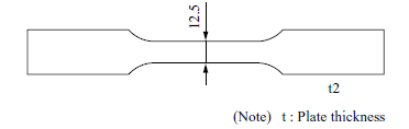
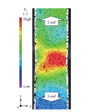
Figure 1 shows the shape of a smooth plate test piece with a plate thickness of 2 mm and parallel section width of 12.5 mm used for the DIC measurement in the tensile test. A preliminary analysis was conducted to check the strain rate, which is an important parameter for identifying burst occurrence. Subsequently, the tensile test was conducted, varying the strain rate from 0.000 1 s−1 to 1 s−1. Figure 2 illustrates typical DIC measurement result. We were able to confirm that strain locally concentrated on the necking section of the test piece was successfully measured. For measurements at strain rates of 0.01 s−1 or higher, images were captured using a high-speed camera to ensure a sufficient frame rate.
2.2 Creation of true stress-true strain relationship
True stress and true strain were obtained using the strain distribution provided through DIC. As shown in Fig. 2, strain has locality. Therefore, in this study, the true stress-true strain relationship was determined by obtaining the average stress and average strain in the cross section at the necking section(2). First, average axial strain  , calculated by averaging axial strain εy in the width direction at an ultimate fracture position identified through DIC was defined as true strain εT.
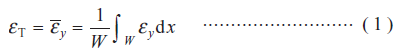
where W and x are the width and direction of the parallel section respectively.
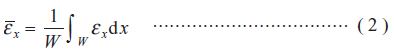
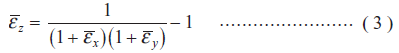
To obtain true stress, it is necessary to account for the change in the cross-sectional area after necking. Although information on the plate thickness is required for calculating the cross-sectional area, the deformation amount in the plate thickness direction cannot be measured with DIC. Therefore, the cross-sectional area was calculated based on the deformation amounts in the axial and width directions, assuming constant volume. First, in addition to the average axial strain  obtained using Equation (1), average width direction strain
  was calculated by averaging width direction strain εx in the width direction at the ultimate fracture position.
Assuming constant volume during plastic deformation, average plate thickness direction strain can be obtained using the following equation.
Thus, the cross-sectional area A at the necking section can be calculated using Equation (4) with the initial cross-sectional area defined as A0 .

In this study, true stress σT was obtained by dividing the test equipment loadFby the cross-sectional areaAcalculated using Equation (4) based on the DIC measurement result.

Figure 3 shows the relationship between the true strain (plastic strain εp) and the true stress obtained from the tensile test.
3. Ductile fracture criterion
3.1 Stress triaxiality and Lode angle parameter
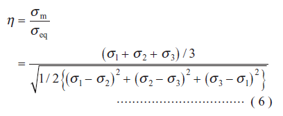
The ductile fracture of metal occurs with inclusions or microscopic voids in metal materials as fracture origin points in a manner where the application of stress causes voids to grow and coalesce with one another, thereby developing into ductile cracks(3), (4) . The growth and coalescence of voids are deeply associated with stress triaxiality which significantly affects fracture strain. The stress triaxiality η is expressed as a ratio of hydrostatic stress σm to von Mises equivalent stress σeq, representing the triaxiality of stress. Using three principal stress components σ1,σ2,σ3, the stress triaxiality η can be expressed by Equation (6).
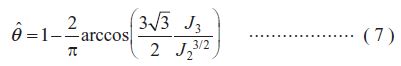
Also, the Lode angle parameter  is the normalized value of Lode angle θL defined as the azimuth direction of stress in a principal stress space and an index representing the proximity to a pure shear state. The Lode angle parameter is also defined by Equation (7) using the second invariant J2 and the third invariant J3 of deviatoric stress and has a particular value of 0 in a state of pure shear, 1 in a state of uniaxial tension or equibiaxial compression and −1 in a state of uniaxial compression or equibiaxial tension(5).
A stress state can be uniquely expressed by the Lode angle parameter and the stress triaxiality. Bai et al. advocated that the new fracture locus function (NFLF) expressed by Equation (8) enables fracture strain to be expressed as a function of the stress triaxiality η and the Lode angle parameter , denoted as  ( 6 ).
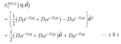
where D1toD6 are undetermined material constants of the NFLF. This study utilized the NFLF because it can effectively express the dependence of fracture strain on stress triaxiality and the Lode angle parameter with a high degree of freedom.
A damage increment dD is defined as the ratio of the increment of equivalent plastic strain dεp under load to the fracture strain obtained with the NFLF. As previously mentioned, the ductile fracture of metal occurs with the growth and coalescence of microscopic voids generated inside base materials under load, ultimately leading to ductile cracks. The growth of voids is influenced by the stress triaxiality η and the Lode angle parameter at each time point when plastic strain εp increases during a loading process. Thus, to take into account the change history of the stress triaxiality and the Lode angle parameter during a loading process, this study utilized a damage indicator D obtained by integrating dD during loading as shown in Equation (9). In this approach, D= 1.0 corresponds to the occurrence of ductile fracture and serves as a ductile fracture criterion ( 7 ).
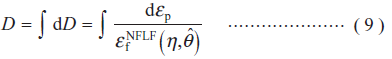
Hereinafter, this criterion is referred to as the NFLF fracture criterion.
3.2 Implementation of coupon tests
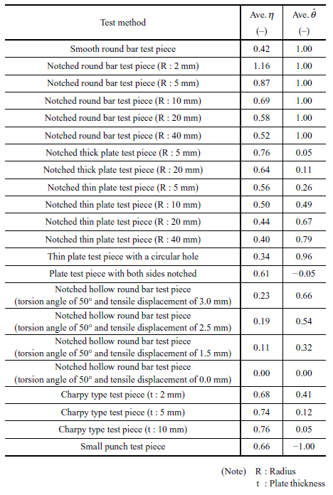
Prediction of burst behavior requires the acquisition of the fracture strain under the region of the stress triaxiality and the Lode angle parameters which may take place on the disk. Thus, coupon tests were implemented using the forged Ti-6Al-4V material by varying loading forms and test piece shapes. Table 1 lists 22 types of coupon tests implemented in this study including the stress triaxiality and the Lode angle parameters of each test piece obtained from the analyses explained in Section 3.3. Also, Fig. 4 shows the shapes of each test piece. Preliminary analyses of coupon tests were conducted to determine test conditions so as to enable six undetermined NFLF material constants to be determined and to facilitate the acquisition of the fracture strain over a large region of the stress triaxiality and the Lode angle parameters.
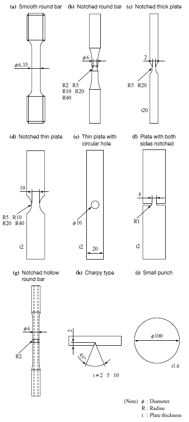
For round bar test pieces and plate test pieces, they were subjected to tensile displacement at a constant rate until their fracture. To control stress states, various notch shapes were utilized, including five types for round bar test pieces, two types for thick plate test pieces, and four types for thin plate test pieces. The notched hollow round bar test pieces were simultaneously subjected to two types of displacement: tensile and torsional, in order to control the stress triaxiality and Lode angle parameters by altering the ratios between the two types of displacement. As for the Charpy type test piece, following some prior research(8), a 3-point bending test with a span of 40 mm was conducted with a pause midway through the test and observation of the cross-sectional structure to measure the deformation amount when ductile cracks developed. The small punch test piece was subjected to equibiaxial tensile stress by pressing a steel ball with a diameter of 50 mm into it.
3.3 Analyses of the coupon tests
The finite element analyses of the coupon tests were conducted using the true stress-true strain relationship established in Chapter 2 as the material constitutive law of forged Ti-6Al-4V material.
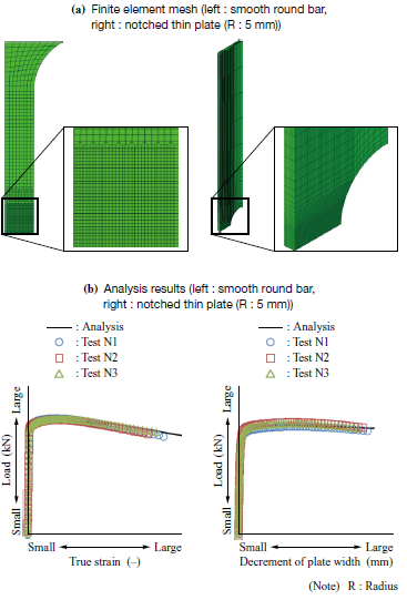
Figure 5 shows typical finite element models used in the analyses. Axisymmetric solid elements were used for modeling the round bar, notched hollow round bar and small punch test pieces. Three-dimensional solid elements were used for modeling Charpy type test pieces and plate test pieces such as notched thick plates, notched thin plates. The mesh size of 0.1 mm was used for the area surrounding an evaluated section in all finite element models. Figure 5 shows the typical relationship between loads and deformations obtained from the analyses of the coupon tests. The analysis results accurately reproduced the test results, demonstrating the validity of the analyses.
The stress triaxiality and Lode angle parameters until fracture in each coupon test were obtained from these analyses. Here, to consider the change history of the stress triaxiality η and the Lode angle parameters during the loading process, they were averaged after integration with plastic strain εp from 0 to fracture strain εf as expressed by the following equations (7).
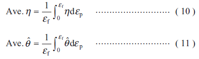
The stress triaxiality η and the Lode angle parameters averaged until fracture of test pieces using Equations (10) and (11) are listed in Table 1.
3.4 Creation of fracture strain expressed in the NFLF
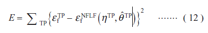
The NFLF was created using the stress triaxiality and the Lode angle parameters obtained from the coupon tests. The error function E defined by Equation (12) was used to determine the six undetermined material constants in Equation (8).
 ,
, and
and are the fracture strain, stress triaxiality and Lode angle parameter of the coupon test. The NFLF material constants were calculated in a manner that minimizes the error function expressed by Equation (12).
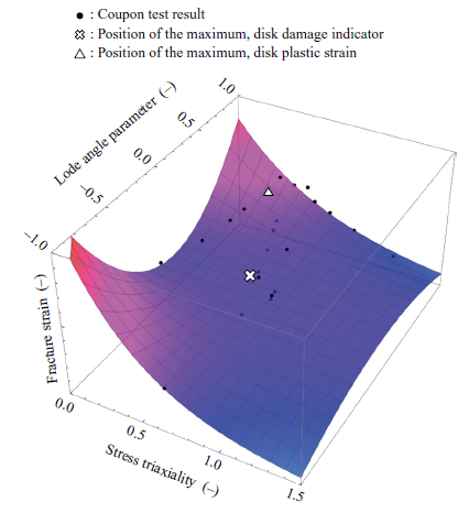
The fracture strain created by using the NFLF is shown in Fig. 6. The fracture strain increased as the stress triaxiality decreased. In particular, it was confirmed that such a tendency was enhanced as the absolute values of the Lode angle parameters increased. Also, it was confirmed that the black dots in the figure, representing the coupon test results, demonstrate a high degree of accuracy in how the fracture strain obtained from the NFLF corresponds well with the coupon test results.
4. Disk burst evaluation
4.1 Disk burst test
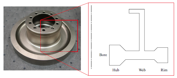
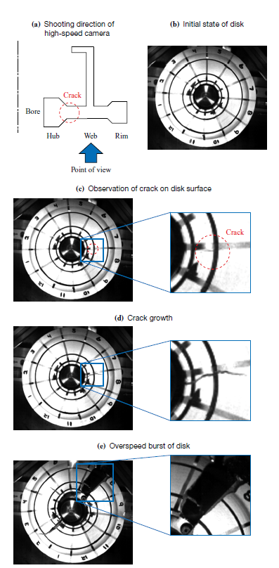
A disk burst test was conducted using a small-diameter disk prepared for the test. Figure 7 shows the shape of the small-diameter disk. It had an external diameter of approximately 150 mm. In the disk burst test, the rotation speed of the disk was increased at a constant rate of acceleration until the disk experienced an overspeed burst. During the test, the displacement of the peripheral section of the disk in the radial direction was measured until the occurrence of overspeed burst. The photographs captured during the disk burst test with a high-speed camera are shown in Fig. 8. In the region inside the inner radius of the web surrounded by the dashed line in Fig. 8-(c), a radial crack opening in a hoop direction was identified on the surface of the disk. Then, the crack grew toward the outer diameter as shown in Fig. 8-(d) and the disk experienced the overspeed burst as shown in -(e).
4.2 Disk burst analysis
A disk burst analysis was conducted by modeling the small-diameter disk using axially symmetric solid elements. The true stress-true strain relationship established in Chapter 2 was used as the material constitutive law for forged Ti-6Al-4V material.
4.3 Discussion
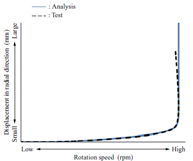
Figure 9 shows the relationship between the rotation speeds and the displacement of the disk peripheral section in the radial direction obtained from both the disk burst test and the disk burst analysis. In the disk burst test, it was observed that the rotational acceleration gradually decreased due to the abrupt increase in moment of inertia associated with the abrupt increase in displacement in the radial direction until the rotation speed peaked. After reaching its peak, the rotation speed decreased. In the disk burst analysis, it was confirmed that displacement until a rotation speed peaks can be predicted with high accuracy although the analysis could not reproduce the subsequent reduction in the rotation speed.
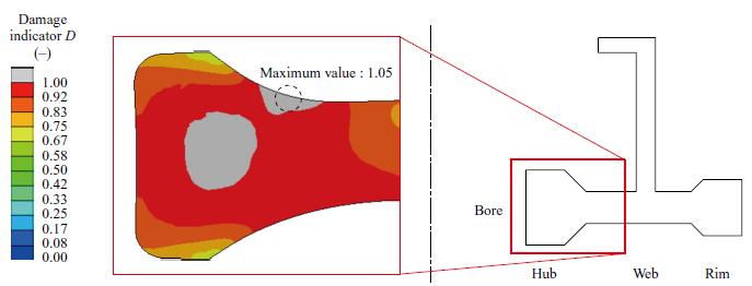
Subsequently, the failure mode of the tested disk was examined. The disk burst analysis clarified the existence of a structural instability point where a structural body cannot be maintained due to accelerated increase in deformation as a result of the increase in the inertia force to a level breaking the balance of forces inside the disk. To verify the presence or absence of fractures inside the disk at the structural instability point, the damage indicator distribution at that point was analyzed as shown in Fig. 10. The position where the damage indicator D is maximized was inside the hub and close to the inner diameter of the web where a crack was observed in the disk burst test. Considering that the maximum value of the damage indicator D was less than 1.0 at 0.76, it was identified that ductile fracture did not occur at the structural instability point. Therefore, it was clarified that the failure mode of the tested disk was a structural instability burst.
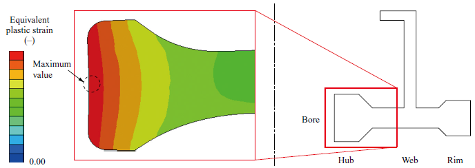
Then, for the purpose of verifying whether or not a fracture origin point in the disk burst test can be predicted, the ductile fracture of materials after their structural instability was examined. Figure 11 shows the damage indicator distribution when a damage indicator D of a material exceeds 1.0. The position of the maximum damage indicator shifted from the location of structural instability, as shown in Fig. 10, towards the outer diameter. Subsequently, the damage indicator was maximized on the disk surface towards the inner diameter of the web. The position was extremely close to the area where the crack was identified in the disk burst test. Figure 12 shows the distribution of equivalent plastic strain at the time when a damage indicator D of a material exceeds 1.0. Unlike the damage indicator, the equivalent plastic strain was maximized at the bore. It was identified that in the tested disk, the states of stress triaxiality and the Lode angle parameters differed between the bore and the inside of the inner diameter of the web. Consequently, the damage indicator D was maximized because a fracture strain  decreased inside the inner diameter of the web.
Based on the above findings, it was clarified that the method established in this study enables structural analyses of overspeed bursts of disks for evaluating ultimate limit state behavior with high accuracy.
5. Conclusion
This study established a method of evaluating the ultimate limit state leading to overspeed burst using a Ti-6Al-4V disk. The findings of this study are summarized as follows.
- The strain of the forged Ti-6Al-4V material during tensile tests was measured using DIC to obtain the true stress-true strain relationship in a high-strain region where necking occurs. The true stress-true strain relationship at a necking section was obtained from the strain distribution measured using DIC.
- Twenty-two types of coupon tests were conducted with stress triaxiality and the Lode angle parameters controlled to obtain the ductile fracture criterion for the forged Ti-6Al-4V material. The fracture strain corresponding to the stress triaxiality and the Lode angle parameters was identified from both the coupon test results and the analysis results of the finite element method. The fracture criterion based on the NFLF for the forged Ti-6Al-4V material was created by using these results.
- Evaluation of the ultimate limit state was conducted for the overspeed burst of a small-diameter disk. The true stress-true strain relationship created using DIC facilitated the analyses to predict the deformation amounts occurred in the disk burst test with high accuracy. The fracture criterion based on the NFLF also enables the prediction of a fracture origin point in the disk with high accuracy.
There have been many discussions on “Certification by Analysis” to reduce development periods and test costs. The industry has been eagerly desiring certifications by analyses for disks to enhance the competitiveness of aero engines. To achieve this goal, it is essential to establish a design method utilizing the technology developed in this study.
REFERENCES
(1) Federal Aviation Administration, Department of Transportation:The Code of Federal Regulations, Title 14: Aeronautics and Space, Chapter I: Federal Aviation Administration, Department of Transportation, Subchapter C: Aircraft, Part 33: Airworthiness Standards: Aircraft Engines,https://www.ecfr.gov/current/title-14/chapter-I/subchapter-C/part-33,accessed 2023-12-24
(2)M. Kawakubo and M. Kamaya : Identification of Inhomogeneous Material Strength near Weld Joint by Three-Dimensional Digital Image Correlation Technique, Transactions of the Japan Society of Mechanical Engineers, Series A, Vol. 79, No. 806, 2013, pp. 1 517-1 529 (in Japanese)
(3) A. A. Benzerga and J. B. Leblond:Ductile fracture by void growth to coalescence,Advances in Applied Mechanics,Vol. 44,( 2010 ),pp. 169-305
(4) T. Yamada and M. Ohata:Prediction of stress triaxiality dependency of critical strain using mechanical properties for metallic materials,International Journal of Pressure Vessels and Piping,Vol. 199,( 2022 ),104 752
(5) M. Dunand and D. Mohr:Effect of Lode parameter on plastic flow localization after proportional loading at low stress triaxialities,Journal of the Mechanics and Physics of Solids,Vol. 66,( 2014 ),pp. 133-153
(6) Y. Bai and T. Wierzbicki:A new model of metal plasticity and fracture with pressure and Lode dependence,International Journal of Plasticity,Vol. 24,Iss. 6,( 2008 ),pp. 1 071-1 096
(7) T. Wierzbicki, Y. Bao, Y. W. Lee and Y. Bai:Calibration and evaluation of seven fracture models,International Journal of Mechanical Sciences,Vol. 47,Iss. 4-5,( 2005 ),pp. 719-743
(8) K. Hirota, D. Tatani, H. Shoji, M. Ohata, Y. Imai and T. Sakanoue : Mathematical ductile damage model for predicting multimode ductile crack growth behavior, Proceedings of Welded Structure Symposium 2017, 2017, pp. 465-472 (in Japanese)