
Material Evaluation Methods with Miniature Specimen
NAKAHARA Yosuke, KIMURA Takahiro
NAKAHARA Yosuke : Materials & Structural Engineering Department, Technology Platform Center, Corporate Research & Development Division
KIMURA Takahiro : Materials & Structural Engineering Department, Technology Platform Center, Corporate Research & Development Division
Material evaluation methods with miniature specimen, which originated in the assessment of degradation in nuclear and thermal power plants, are now applied in diverse industrial fields, including the evaluation of weld joints and biomaterials. In particular, the small punch test is relatively easy in terms of preparation from miniature specimens and is effective for evaluating various mechanical properties. This paper describes the methods, fundamental principles, and applicability of the small punch test.
1. Introduction
A material evaluation method using miniature specimens has been developed and advanced primarily for assessing degradation and damage to structural components in nuclear and thermal power plants(1) – (3). In recent years, it has also been applied to other industrial fields, including the evaluation of mechanical properties of welded joints, biomaterials for implants, and mechanical properties for aero engine materials(4) – (7). To ensure the safety and reliability of structures, evaluating actual products is effective, and evaluation methods appropriate to their size are required.
Test methods using miniature specimens include the sub-size standard test(8) – (11), which uses downsized standard specimens, the indentation test(12), and the small punch (SP) test(13), (14). The SP test enables evaluation using thin specimens with a thickness of 1 mm or less. The processing of the specimens is easier than that required for sub-size standard tests, which require processing into a dog bone shape or an hourglass shape. Test methods such as the small punch creep (SPC) test(15) for evaluating characteristics and the small bulge fatigue (SBF) test(16) for evaluating fatigue characteristics were also developed from the SP test. Many studies on these test methods have been conducted mainly for metallic materials. In those studies, it has been revealed that the properties obtained from the methods correlate with mechanical properties such as ultimate tensile strength, creep, fatigue, and fracture toughness(13) – (19).Therefore, these methods are expected to be used in a wider range of industrial fields. This paper describes the method, basic principle, and usefulness of the SP test.
2. Small punch test
Figure 1 shows a schematic of the SP test. In the SP test, a thin disk-shaped specimen is clamped between an upper die and a lower die, and a cylindrical punch is pressed into the specimen to break it. The typical specimens used in the SP test have a diameter of 3 to 10 mm and a thickness of 0.5 mm. They require less material than uniaxial tensile specimens and allow for localized evaluation.
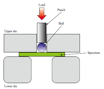
In the SP test, the specimen is deformed non-uniformly due to bending and membrane elongation caused by indentation. This leads to a multiaxial state of stress and strain(3), (17), (18), which complicates the interpretation of the results. Figure 2 shows a typical load-displacement curve obtained by the SP test of a metallic material. This is interpreted based on previous experimental and analytical studies as follows(20), (21).
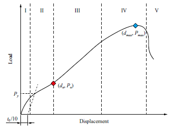
- Region I : The entire specimen is elastically deformed
- Region II : Elastic deformation transitions to plastic deformation
- Region III : The membrane elongates due to multiaxial stresses
- Region IV : The thickness of the specimen decreases and voids form and grow due to plastic instability
- Region V : Cracks grow, causing rupture
Many researchers have been attempting to formulate the mechanical properties estimated from the SP test results(3), (13), (18). For example, García et al.(18) performed SP tests using specimens cut to a thickness of 0.5 mm, as well as tensile tests according to ASTM E8, on stainless steel and aluminum alloys, and proposed Equations (1) and (2) to estimate yield stress and ultimate tensile strength, respectively.
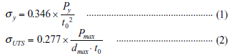
where t0 is the initial thickness of the specimen, and Py is the intersection of the load-displacement curve and a straight line that is tangent to this curve at the origin and offset by t0 /10 on the horizontal axis. Pmax and dmax are the maximum load and resulting displacement, respectively, on the load-displacement curve. The yield stress estimation Equation (1) eliminates the effect of thickness by dividing Py by t0
2, thereby reducing the impact of variations in sample preparation. The ultimate tensile strength estimation Equation (2) uses not only t0 but also the displacement dmax at maximum load, taking into account the decrease in thickness of the specimen before maximum load is reached.
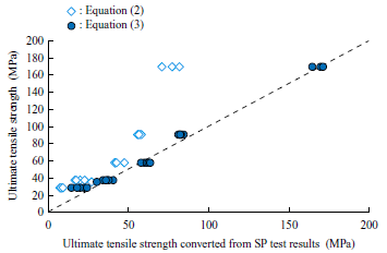
To expand the scope of application of the SP test, which had previously been studied on metal materials, Ota et al.(22) performed SP tests and tensile tests on multiple resins, verifying the applicability of the SP test for evaluating the mechanical properties of resin materials. As a result, they confirmed that the 0.2% proof stress could be converted in the same way using Equation (1). However, ultimate tensile strength could not be expressed using Pmax and dmax in Equation (2). Therefore, they attempted to convert them using the following Equation (3) with Pa and da as the load and displacement at the transition point from region II to region III.

Figure 3 shows the ultimate tensile strength of various resin materials converted from SP test results using Equations (2) and (3). While the ultimate tensile strength converted using Equation (2) was lower than the tensile test results, those converted using Equation (3) agreed relatively well. It can be considered that the reason for using the transition point from region II to region III is to avoid deformation under multiaxial stresses and plastic instability after region III.
Other methods have also been proposed for estimating elastic modulus(23) and fracture toughness(24), (25) by applying SP tests.
Thus, although interpreting the results is complicated, the SP test is effective in evaluating materials with limited volume and small parts of products, and its results correlate well with the material’s mechanical properties.
3. Small punch creep test
The SPC test is performed in an electric furnace heated to the test temperature by applying a constant load F via a ball and a punch to the center of a thin disk-shaped specimen clamped between upper and lower dies. This method allows measuring the displacement of the specimen during the test, as well as the rupture time of the specimen. The shapes of the specimen and jig are basically the same as those in the SP test (Fig. 1). However, since the test is performed while heating in an electric furnace, an inert gas, such as argon (Ar), is flowing around the specimen to prevent oxidation. The typical shape of an SPC specimen is a disk measuring 7 to 10 mm in diameter or a 10 mm square plate, with a thickness of 0.5 mm(26).
Kubushiro et al.(27) verified a method for remaining life assessment of welded joints by performing uniaxial creep tests and SPC tests on 2.25Cr-1Mo steel welded joints used in thermal power boilers. This method revealed that the cumulative damage D given by the following Equation (4), with Dc as the creep damage rate and Dsp as the creep damage rate by the SPC test, falls within the range of 0.8 to 1.2. Figure 4 shows the evaluation results of creep damage and SPC damage based on the linear damage rule.
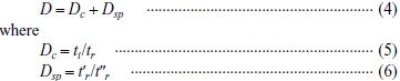
ti is the test time until the uniaxial creep test was interrupted, tr is the rupture time in the uniaxial creep test, t′r is the rupture time in the SPC test performed using the material taken from the specimen used for the uniaxial creep test interrupted at ti, and t″r is the rupture time in the SPC test performed on the new specimen taken from the same material as the welded joint that was the uniaxial creep specimen.
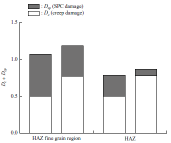
Using this relationship, the creep damage rate Dc can be evaluated through the SPC test. Even when the specimen was taken in such a way that it included both the base metal and weld metal so that the heat affected zone (HAZ) was distributed in the center of the SPC specimen, the cumulative damage was in the range of 0.8 to 1.2. This suggests that remaining creep life assessment is possible for actual welded joints by sampling from the surface.
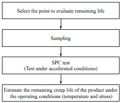
The SPC test evaluates creep properties. However, as mentioned above, it applies load F instead of stress σ. Therefore, to compare the results with those of a normal uniaxial creep test, the load must be converted into stress. Many methods have been proposed for the load/stress conversion equation F/σ, including those using Fm (maximum load), um (displacement at maximum load), and specimen thickness obtained from the SP test results(28), and those using umc (displacement when minimum displacement rate is reached in an SPC test)(29), (30). Figure 5 shows the flow of the remaining creep life assessment by the SPC test. By converting to appropriate stress conditions using the method described above, this can be applied to the remaining creep life assessment of actual products in the same way as ordinary uniaxial creep tests.
4. Small bulge fatigue test
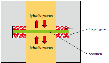
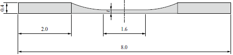
The SBF test was developed by Komazaki et al.(16) to evaluate fatigue properties using disk-shaped specimens. Figure 6 shows a schematic of the SBF test. A hydraulic chamber is provided adjacent to the specimen clamped with copper gaskets, which is designed to apply a load to the specimen in the through-thickness direction using hydraulic pressure. Switching the servo valve alternately applies a constant hydraulic pressure from both sides of the specimen, thereby achieving a double-sided fatigue test. The cross-sectional shape and dimensions of the SBF specimen are shown in Fig. 7. The specimen is flat on one side and concave on the other to prevent fracture due to stress concentration at the clamping location with copper gaskets. In addition, it is possible to retain the material surface which is considered to affect the fatigue life by making one side of the specimen flat.
Since the SBF test results in multiaxial stress as well as the SP and SPC tests, several procedures are required to compare the results of the SBF test with those of the uniaxial stress fatigue test. The following is a case study of the nickel (Ni)-based Inconel® 718. The SBF test is performed by setting the equipment to automatically stop when the pressure in the hydraulic chamber drops to a certain value. After the automatic stop, radial cracks will be observed from the center of the specimen, and in some cases, chipping will also be observed. In other words, the test ends when the specimen ruptures. During the test, strain is measured by the strain gauge attached near the center of the flat side of the specimen. Incidentally, when the strength level of the material to be tested is significantly higher than that of the strain gauge, as is the case here, it can be considered that attaching the strain gauge will not affect the material’s life.
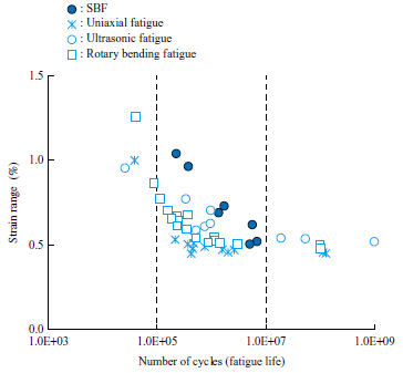
Figure 8 shows the relationship between strain and the number of cycles (fatigue life) until rupture in SBF tests conducted with various thicknesses t of the center of the specimen and pressures. The results of conventional fatigue tests (uniaxial fatigue, ultrasonic fatigue, and rotary bending fatigue tests) are also plotted in Fig. 8. Although a certain correlation is observed between the two fatigue lives, the fatigue life of the SBF test shifted to a longer life than that of the conventional fatigue test.
Yoshizaki et al.(31) performed SBF tests on SUS316 and reported that by normalizing the fatigue life by the ratio of surface crack lengths, the results agreed with those of uniaxial fatigue tests. Similarly, IHI attempted to normalize the SBF test results of Inconel 718. The number of cycles at which the crack length reaches 1.6 mm, which corresponds to the parallel portion of the SBF specimen, is set to N1.6. If this is defined using the fatigue life Nf (SBF) of the SBF test or the fatigue life Nf (UA) of the uniaxial fatigue test, the following relationship is obtained.

From this relationship, the following conversion Equation (9) is obtained.

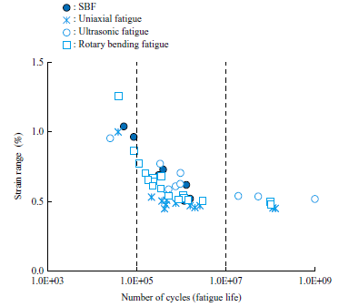
The results of normalization using Equation (9) are shown in Fig. 9. The figure shows that the fatigue life in the SBF test is in good agreement with the results of conventional fatigue tests. Thus, the SBF test is effective for evaluating the fatigue properties of materials, suggesting the possibility of predicting fatigue life. We plan to develop test methods for higher temperatures in the future.
5. Conclusion
This paper introduced a method for evaluating materials using miniature specimens, with a focus on the SP test. In the SP test, the ruptured part is in a multiaxial state due to the specimen’s shape and the loading method. Consequently, rupture strength varies from test to test, and it is necessary to calculate the relative lifetime by comparing the results with those of uniaxial tests. However, when evaluating the remaining life of a structure, it is possible to obtain a more accurate understanding of deterioration using actual materials. For this reason, material evaluation methods using miniature specimens, such as the SP test, which allows easy preparation of specimens and has little impact on the actual products after sampling, are effective for evaluating the local mechanical properties of structural components. We will continue to work on verifying the applicability of test methods, improving their accuracy, and developing them toward standardization.
REFERENCES
(1) S. Misawa : Progress in fine material test piece evaluation technology, Bulletin of the Japan Institute of Metals, Vol. 31, No. 11, 1992, pp. 1,008-1,009 (in Japanese)
(2) M. P. Manahan, A. S. Argon and O. K. Harling : The development of a miniaturized disk bend test for the determination of postirradiation mechanical properties, Journal of Nuclear Materials, Vol. 104, 1981, pp. 1,545-1,550
(3) E. Fleury and J. S. Ha : Small punch tests to estimate the mechanical properties of steels for steam power plant: I. Mechanical strength, International Journal of Pressure Vessels and Piping, Vol. 75, Iss. 9, 1998, pp. 699-706
(4) C. Rodríguez, J. G. Cabezas, E. Cardenas, F. J. Belzunce and C. Betegón : Mechanical properties characterization of heat-affected zone using the small punch test, Welding Journal, Vol. 88, No. 9, 2010, pp. 188-192
(5) H. G. Svoboda, M. Duran, F. J. Belzunce and C. Rodríguez : Estimation of Local Mechanical Properties by Small Punch Test in Welded Joints of Maraging C250 Steel, Journal of Materials Engineering and Performance, 2024
(6) V. L. Giddings, S. M. Kurtz, C. W. Jewett, J. R. Foulds and A. A. Edidin : A small punch test technique for characterizing the elastic modulus and fracture behavior of PMMA bone cement used in total joint replacement, Biomaterials, Vol. 22, Iss. 13, 2001, pp. 1,875-1,881
(7) R. C. Hurst, R. J. Lancaster, S. P. Jeffs and M. R. Bache : The contribution of small punch testing towards the development of materials for aero-engine applications, Theoretical and Applied Fracture Mechanics, Vol. 86, Part A, 2016, pp. 69-77
(8) N. Kashaev, M. Horstmann, V. Ventzke, S. Riekehr and N. Huber : Comparative study of mechanical properties using standard and micro-specimens of base materials Inconel 625, Inconel 718 and Ti-6Al-4V, Journal of Materials Research and Technology, Vol. 2, Iss. 1, 2013, pp. 43-47
(9) S. Nogami, W. Guan, M. Toyota, and A. Hasegawa : Fatigue life prediction of ferritic/martensitic steels based on universal slope equations and tensile properties obtained using small specimen, Fusion Engineering and Design, Vol. 125, 2017, pp. 330-336
(10) S. Nogami, A. Nishimura, E. Wakai, H. Tanigawa, T. Itoh and A. Hasegawa : Development of fatigue life evaluation method using small specimen, Journal of Nuclear Materials, Vol. 441, Iss. 1-3, 2013, pp. 125-132
(11) P. Zheng, R. Chen, H. Liu, J. Chen, Z. Zhang, X. Liu and Y. Shen : On the standards and practices for miniaturized tensile test – A review, Fusion Engineering and Design, Vol. 161, 2020
(12) S. Arunkumar : A Review of Indentation Theory, Materials Today: Proceedings, Vol. 5, Iss. 11, Part 3, 2018), pp. 23,664-23,673
(13) X. Mao and H. Takahashi : Development of a further-miniaturized specimen of 3 mm diameter for tem disk (ø3 mm) small punch tests, Journal of Nuclear Materials, Vol. 150, Iss. 1, 1987, pp. 42-52
(14) E. N. Campitelli, P. Spätig, R. Bonadé, W. Hoffelner and M. Victoria : Assessment of the constitutive properties from small ball punch test: experiment and modeling, Journal of Nuclear Materials, Vol. 335, Iss. 3, 2004, pp. 366-378
(15) B. Ule, T. Šuštar, F. Dobeš, K. Milička, V. Bicego, S. Tettamanti, K. Maile, C. Schwarzkopf, M. P. Whelan, R. H. Kozlowski and J. Klaput : Small punch test method assessment for the determination of the residual creep life of service exposed components: outcomes from an interlaboratory exercise, Nuclear Engineering and Design, Vol. 192, Iss. 1, 1999, pp. 1-11
(16) S. Komazaki, R. Jojima, N. Muraoka, S. Nogami, M. Kamaya, C. Hisaka, M. Fujiwara and A. Nitta : Development of small bulge fatigue testing technique using small disk-type specimen, Fatigue & Fracture of Engineering Materials & Structures, Vol. 43, Iss. 3, 2020, pp. 444-456
(17) E. Altstadt, H. E. Ge, V. Kuksenko, M. Serrano, M. Houska, M. Lasan, M. Bruchhausen, J. -M. Lapetite and Y. Dai : Critical evaluation of the small punch test as a screening procedure for mechanical properties, Journal of Nuclear Materials, Vol. 472, 2016, pp. 186-195
(18) T. E. García, C. Rodríguez, F. J. Belzunce and C. Suárez : Estimation of the mechanical properties of metallic materials by means of the small punch test, Journal of Alloys and Compounds, Vol. 582, 2014, pp. 708-717
(19) M. Abendroth and S. Soltysiak : Assessment of Material Properties by Means of the Small Punch Test, Recent Trends in Fracture and Damage Mechanics, Springer, 2016, pp. 127-157
(20) S. Rasche and M. Kuna : Improved small punch testing and parameter identification of ductile to brittle materials, International Journal of Pressure Vessels and Piping, Vol. 125, 2015, pp. 23-34
(21) M. Abendroth and M. Kuna : Determination of deformation and failure properties of ductile materials by means of the small punch test and neural networks, Computational Materials Science, Vol. 28, Iss. 3-4, 2003, pp. 633-644
(22) Y. Ota, Y. Nakahara and Y. Sakakibara : Evaluation of Tensile Properties of Thermoplastic and Thermosetting Resins Using Small Samples with Small Punch Test, Journal of the Society of Materials Science, Japan, Vol. 72, No. 8, 2023, pp. 599-605 (in Japanese)
(23) J. C. Chica, P. M. B. Díez and M. P. Calzada : Improved correlation for elastic modulus prediction of metallic materials in the Small Punch Test, International Journal of Mechanical Sciences, Vol. 134, 2017, pp. 112-122
(24) J. M. Alegre, R. Lacalle, I. I. Cuesta and J. A. Álvarez : Different methodologies to obtain the fracture properties of metallic materials using pre-notched small punch test specimens, Theoretical and Applied Fracture Mechanics, Vol. 86, Part A, 2016, pp. 11-18
(25) I. I. Cuesta, A. Willig, A. Díaz, E. Martínez-Pañeda and J. M. Alegre : Pre-notched dog bone small punch specimens for the estimation of fracture properties, Engineering Failure Analysis, Vol. 96, 2019, pp. 236-240
(26) The Society of Materials Science, Japan : Standards for Small Sample Creep Test for Remaining Life Assessment of High-temperature Equipment, 2012 (in Japanese)
(27) K. Kubushiro and H. Yoshizawa : Small Punch Creep Life Assessment of 2.25Cr-1Mo Steel Weldment, Journal of IHI Technologies, Vol. 47, No. 4, 2007 (in Japanese)
(28) S. Komazaki, K. Obata, M. Yaguchi, M. Kanai, M. Tomobe and A. Kumada: Creep Property Assessment of 9Cr Steel Boiler Piping by Small Punch Test, Journal of the Society of Materials Science, Japan, Vol. 70, No. 2, 2021, pp. 125-132 (in Japanese)
(29) P. Dymáček, Y. Li, F. Dobeš and P. Stevens : New approach to determine uniaxial creep properties from small punch creep curves, Materials at High Temperatures, Vol. 36, Iss. 2, 2018, pp. 157-164
(30) S. Holmström, Y. Li, P. Dymacek, E. Vacchieri, S. P. Jeffs, R. J. Lancaster, D. Omacht, Z. Kubon, E. Anelli, J. Rantala, A. Tonti, S. Komazaki, Naveena, M. Bruchhausen, R. C. Hurst, P. Hähner, M. Richardson and D. Andres : Creep strength and minimum strain rate estimation from Small Punch Creep tests, Materials Science and Engineering: A, Vol. 731, 2018, pp. 161-172
(31) K. Yoshizaki, S. Komazaki, M. Kamatani, S. Nogami, N. Muraoka, T. Hisaka and A. Nitta : Development of Small Bulge Fatigue Testing Technique, Proceedings of M&M Materials Mechanics Conference, JSME, 2018 (in Japanese)