
Component-Level Technology Demonstration of Resin-Based Lightweight Acoustic Liner on the JAXA F7 Engine Testbed
KAGAYA Ryo, OISHI Tsutomu, YAMANAKA Shohei
KAGAYA Ryo : Advanced Technology Department, Research & Engineering Division, Aero Engine, Space & Defense Business Area
OISHI Tsutomu : Manager, Advanced Technology Department, Research & Engineering Division, Aero Engine, Space & Defense Business Area
YAMANAKA Shohei : Manager, Engine Technology Department, Research & Engineering Division, Aero Engine, Space & Defense Business Area
The acoustic liner is one of the most essential devices for reduction of noise emitted by high bypass ratio turbofan engines. IHI has developed and demonstrated lightweight acoustic liner technology utilizing thermoplastic resin for a future turbofan engine together with Japan Aerospace Exploration Agency (JAXA). In 2022, the component-level technology demonstration was conducted with the acoustic liner mounted on the F7-10 engine testbed of JAXA. The demonstration showed that the acoustic liner can achieve the sound absorption performance and structural soundness under actual engine operating conditions. It was also successfully demonstrated that the manufacturing technology was established to ensure both the lightweightness and structural strength enough to be used under engine operating conditions.
1. Introduction
There are strong demands for civil aircraft to ensure environmental compatibility, with noise reduction being one of the most important indicators of this compatibility. Existing civil aircraft must comply with the noise standards outlined in ICAO Annex 16, Volume I, Chapter 14, established in 2013 by the International Civil Aviation Organization (ICAO), a United Nations agency(1). These standards have applied to aircraft with a maximum takeoff weight of 55 t or more since December 31, 2017, and to aircraft with a maximum takeoff weight of less than 55 t since December 31, 2020. The history of the noise regulation values for civil aircraft is shown in Fig. 1. The noise regulation values for civil aircraft have become progressively stricter over the years. Additionally, in recent years, there has been growing demand to reduce CO₂ emissions from aircraft engines, alongside the accelerated movement toward carbon neutrality in air transport. At its 41st general meeting held in 2022, the ICAO adopted a long-term global aspirational goal (LTAG) for the international aviation sector of net-zero carbon emissions by 2050(2). The jet engines to be used in future civil aircraft will require the development and practical implementation of technologies to achieve both high levels of quietness and reduced CO₂ emissions.
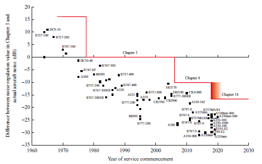
Jet engines are the primary source of noise in an aircraft. For high bypass ratio turbofan engines (high bypass ratio engines), which have been commonly used in civil aircraft, the fans installed at the front of the engines are the primary source of noise. As an important and effective part to reduce noise emitted from fans (fan noise), the acoustic liner, which is the subject of this research, has been applied on a wide area, including the wall surfaces of fan ducts on high bypass ratio engines. However, while the acoustic liner is effective in reducing fan noise, its weight has the disadvantage of deteriorating fuel economy. As future high bypass ratio engines are expected to require larger-diameter fans to enhance performance, the weight of the acoustic liner will increase accordingly. Therefore, it is essential for the acoustic liner to be lightweight.
This research, aimed at reducing the weight of the acoustic liner compared to conventional ones while maintaining noise reduction performance, focuses on the development of a technology for creating an acoustic liner structure using lightweight thermoplastic resin (resin-based lightweight acoustic liner). After demonstrating various element technologies, an engine demonstration with the resin-based lightweight acoustic liner was conducted from May to July 2022. As a result, this research confirmed the noise reduction performance and structural soundness under actual engine operating conditions and demonstrated manufacturing technologies that achieve both weight reduction and structural durability enough to be used for engine tests. This paper outlines the technologies for the resin-based lightweight acoustic liner and the results of the engine demonstration.
2. Technologies for the resin-based lightweight acoustic liner
2.1 Acoustic liner
Figure 2 shows a typical structure of the acoustic liner. The acoustic liner consists of a perforated surface plate, a core section (with a honeycomb or cell structure that provides sufficient strength), and an unperforated back plate. This configuration is also known as a honeycomb sandwich panel structure. The acoustic liner uses the principle of Helmholtz resonance, which occurs when acoustic waves incident on the perforated surface plate propagate inside the honeycomb core. Helmholtz resonance causes the gas inside the holes on the perforated surface plate to oscillate significantly, and the energy of the acoustic waves is dissipated as heat generated by friction from the oscillation, thereby attenuating the acoustic waves. This is the sound absorption mechanism through Helmholtz resonance.
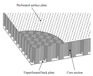
The acoustic liner used in conventional high bypass ratio engines consists of metals such as aluminum alloys and composite materials including fiber reinforced plastic (FRP). In particular, aluminum alloys are commonly used for the core sections.
2.2 Resin-based lightweight acoustic liner
This research involved the development of a resin-based lightweight acoustic liner with a honeycomb sandwich panel structure molded from PA6 (nylon 6) based thermoplastic resin. In this research, PA6-based thermoplastic resin, which is lighter than metal or FRP, was adopted for the development of the acoustic liner. Additionally, considering the possibility of the acoustic liner being subjected to impact loads when a jet engine ingests foreign objects, a grade of PA6-based thermoplastic resin with excellent impact resistance was selected, highlighting the importance of durability under such conditions.
Similar to a conventional acoustic liner, the structure of the resin-based lightweight acoustic liner consists of a perforated surface plate, a honeycomb core section, and an unperforated back plate. However, the resin-based lightweight acoustic liner is manufactured by molding a honeycomb shape from a thin thermoplastic resin sheet, forming the core section with the honeycomb shape, and welding it to the perforated surface plate and the plate that forms the unperforated back plate. These manufacturing processes are more advantageous for weight reduction, as they eliminate the need for the adhesive joining process that is essential in manufacturing conventional acoustic liners made of a combination of materials.
However, thermoplastic resin and its molded products have the disadvantages of being lower in strength compared to metallic and FRP materials, as well as challenges in maintaining the dimensional accuracy of molded products. As described in Section 2.3, in the early stages of this research, a molding technology was developed to overcome these disadvantages, and various fundamental demonstration tests were conducted to confirm that noise reduction performance, structural soundness, and manufacturing feasibility meet the required criteria.
2.3 Fundamental development of technologies for the resin-based lightweight acoustic liner : aFJR Project
The development of the resin-based lightweight acoustic liner began as part of the Advanced Fan Jet Research (aFJR) Project implemented by the Japan Aerospace Exploration Agency (JAXA)(3). The technologies for the resin-based lightweight acoustic liner were thus jointly developed by JAXA and IHI as technologies contributing to the weight reduction of the fan module.
In the aFJR Project, a full-scale test specimen with the dimensions of an actual engine was fabricated and subjected to demonstrations of structural soundness, as well as acoustic performance evaluations through a flow duct acoustic test and a fan rig acoustic test(3), (4). In addition to demonstrating the performance of the established manufacturing technologies, the aFJR Project also showed that the resin-based lightweight acoustic liner offers both noise and weight reduction, as well as the basic strength and durability required for practical use. For details on the outcomes of the aFJR Project, please refer to REFERENCES(3), (4).
3. Engine demonstration test
3.1 Purpose of the engine demonstration test
The practical application of the resin-based lightweight acoustic liner to high bypass ratio engines in the future requires technical demonstrations under conditions closer to actual operating environments. In this research, an engine demonstration test was conducted to technically validate the performance of the resin-based lightweight acoustic liner under the harsh environment unique to jet engines, characterized by high noise levels, high air flow speeds, and intense vibrations, which pose significant challenges for an acoustic liner(5), (6).
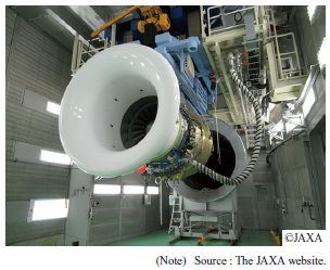
The engine demonstration test was conducted with an F7-10(7) (the JAXA F7 engine) as a testbed. Figure 3 shows the external appearance of the JAXA F7 engine. JAXA adopted the F7 engine in 2019 to demonstrate an original technology researched and developed domestically. In 2021, it was used to demonstrate the performance of a shroud made of ceramic matrix composite (CMC) with heat resistance up to 1,400°C(8). The research marked the second use of the engine for technical demonstration and the first for showcasing the performance of a fan section. The demonstration test was conducted at JAXA’s ground-level enclosed jet engine test facility.
3.2 Designs for engine demonstration test
In the engine demonstration test, various designs were implemented to evaluate the performance of a resin-based lightweight acoustic liner mounted on an engine fan case. Figure 4 illustrates the location on the JAXA F7 engine where the test specimen of the resin-based lightweight acoustic liner was installed. To ensure the potential applicability of the resin-based lightweight acoustic liner to high bypass ratio engines in the future, the acoustic design for the engine demonstration test was developed under the constraint that the resin-based lightweight acoustic liner must meet the requirements for strength and impact resistance regardless of its mounting location within the fan case or fan duct. Additionally, to minimize the risks associated with mounting the resin-based lightweight acoustic liner on the JAXA F7 engine, the radial thickness of its main body was set to match that of the standard acoustic liner (F7 acoustic liner) typically installed on the engine. Within these constraints, the acoustic design was optimized to maximize sound absorption.
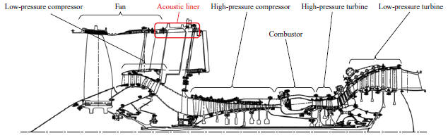
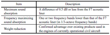
Table 1 presents the predicted performance of the resin-based lightweight acoustic liner designed according to the aforementioned guidelines. The maximum sound absorption of the resin-based lightweight acoustic liner was nearly identical to that of the F7 acoustic liner, but due to the above-mentioned constraints, the frequency corresponding to the maximum sound absorption was predicted to be one or two frequency bands lower in the 1/3-octave frequency bands. In terms of weight, it was confirmed that the resin-based lightweight acoustic liner offers an advantage over existing products used in the engines of currently operational civil aircraft.
3.3 Preliminary demonstration of strength
After the completion of the design for the engine demonstration test, various strength tests were conducted to confirm that the resin-based lightweight acoustic liner can maintain its soundness under engine operation environments without damage or failure. This section introduces two representative tests from these evaluations.
3.3.1 Airflow peeling test
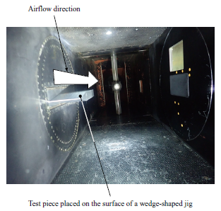
An acoustic liner installed in an engine is exposed to high-speed airflow within the fan duct. When this high-speed airflow strikes the upstream edge of the acoustic liner, depending on the protrusion of the upstream edge into the airflow passage from engine components, the airflow can cause peeling forces to act on the perforated surface plate. Therefore, a strength test under high-speed airflow was conducted to verify that the perforated surface plate would not peel off during engine operation.
The test was conducted in the flutter wind tunnel owned by JAXA. A test specimen of the resin-based lightweight acoustic liner was placed in the wind tunnel and exposed to airflow conditions simulating the maximum Mach number and total pressure expected during the engine demonstration test. The ventilation period was set to 30 seconds, taking into account the need to confirm performance in a static state after the transition period when the test specimen deforms within the limitations of the wind tunnel. Figure 5 shows the conditions inside the wind tunnel. The test specimen remained undamaged for the duration of the test. Additionally, it was confirmed that the test specimen showed no signs of damage, as the deformation measured with a strain gauge placed on the back face of the test specimen was minor and stable throughout the ventilation period.
3.3.2 Vibration test
The vibrations generated by the engine during operation propagate to the acoustic liner through the structures fastening it to the engine components, causing excitation forces to act on the acoustic liner. The excitation force during engine operation can exceed 10 g (approximately 98 m/s2). Therefore, it was necessary to verify the durability of the resin-based lightweight acoustic liner against vibrations.
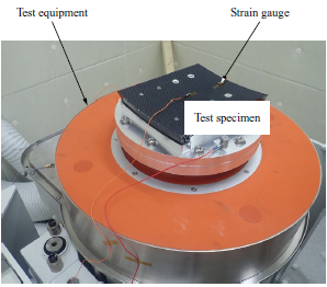
In this research, a vibration test was conducted on a test specimen simulating an acoustic liner to be used in the engine demonstration test, using the vibration test machine owned by JAXA. Figure 6 shows the situation of the vibration test. The vibration acceleration was set based on the actual measurements during engine operation with reference to MIL-STD-810(9). Additionally, the frequency condition for vibration acceleration was set to the resonant frequency determined from the vibration characteristics investigation conducted via frequency sweep prior to the vibration test. For instance, acceleration of 20 g was applied to the resonance mode at approximately 300 Hz. The vibration cycle was set to 107 cycles based on consultations with experts in structural design. In the vibration test, the resin-based lightweight acoustic liner did not show significant changes in vibration characteristics, even when subjected to vibrations in multiple resonance modes. Therefore, it was concluded that no damage would be incurred on the acoustic liner body or the fastening structure sections assumed to be used for securing the acoustic liner to the engine fan frame.
4. Contents of engine demonstration test
4.1 Test specimen of acoustic liner
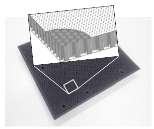
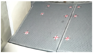
Figure 7 shows the test specimen of the resin-based lightweight acoustic liner used in the engine demonstration test. The test specimen of the resin-based lightweight acoustic liner was fabricated using the same process as the test specimen that met the requirements in the above-described preliminary demonstration for strength testing. As a result of measuring the weight of the fabricated test specimen, it was confirmed that the resin-based lightweight acoustic liner met the weight reduction target as designed. In the engine demonstration test, a strain gauge was placed on the back face of the test specimen of the resin-based lightweight acoustic liner to monitor strain caused by vibrations during engine operation. Additionally, along with the test specimen of the resin-based lightweight acoustic liner, which is the test subject, other test specimens such as the F7 acoustic liner and an unperforated resin panel with no sound absorption effect (hard wall) were tested for comparison purposes. The test specimens of the resin-based lightweight acoustic liner and the hard wall were newly fabricated for the engine demonstration test. Both were successfully mounted on the engine. Figure 8 shows the test specimen of the resin-based lightweight acoustic liner mounted on the engine.
4.2 Measured items
In the engine demonstration test, in addition to the regular measurement of engine performance carried out in the ground-level enclosed jet engine test facility, acoustic measurement was conducted at the fan duct and on the surface of the wall in the engine test room.
4.2.1 Measurement of engine system
As part of the engine system measurements, parameters including the fan rotation speed, mass flow rate into the engine were measured. The fan rotation speed was corrected based on the total pressure and temperature at the engine inlet, and the corrected rotation speed was used to set the engine operating conditions.
4.2.2 Acoustic measurement
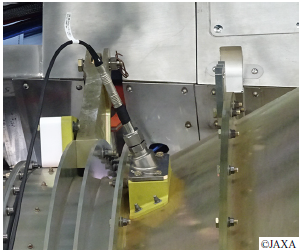
To evaluate the sound absorption performance of the resin-based lightweight acoustic liner, acoustic measurement was carried out inside the fan duct downstream of the acoustic liner. The acoustic measurement was conducted using microphones with a tip diameter of 6.35 mm (1/4 inch). The microphones were installed using a special jig to ensure that their tips were flush with the wall of the fan duct. Figure 9 shows the installation condition of the microphones. The microphones were installed at four circumferential locations at the same axial position, and the acoustic measurement was then conducted simultaneously with all four locations. The acoustic measurement results were converted into sound pressure levels expressed in 1/3-octave frequency bands, and the average of the measurements from the four locations around the circumference was calculated. The acoustic measurement was repeated three times for each test specimen, and the average of the three measurements was used as the final sound pressure level for each test specimen.
5. Engine demonstration test results
5.1 Engine performance evaluation
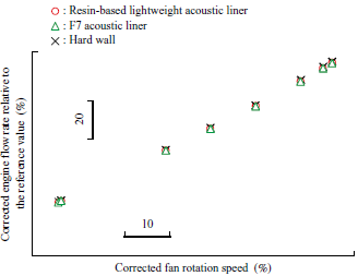
To clarify the influence of the resin-based lightweight acoustic liner on engine operation, the corrected engine flow rates were investigated for each test specimen mounted on the engine, by changing the engine operating conditions. Figure 10 shows the relation between the corrected fan rotation speeds and the corrected engine flow rates. This figure shows the results for all engine operating conditions, ranging from idling to thrust at takeoff. It was confirmed that there was no significant difference in the engine flow rates among the test results for all engine operation conditions with the test specimens of the resin-based lightweight acoustic liner, the F7 acoustic liner, and the hard wall. It was also observed that the pressure loss caused by the test specimen of the resin-based lightweight acoustic liner was sufficiently small to have no significant effect on engine operation.
5.2 Evaluation of sound absorption performance
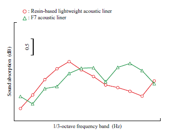
Figure 11 shows the sound absorption of the test specimens of the resin-based lightweight acoustic liner and the F7 acoustic liner. In this evaluation, the differences in sound pressure levels between when the engine was operated with the test specimen of the resin-based lightweight acoustic liner and when the engine was operated with the test specimen of the hard wall were used to evaluate the sound absorption of the resin-based lightweight acoustic liner. The same applies to the evaluation of the sound absorption of the F7 acoustic liner. Figure 11 shows the test results with the engine operated at low rotation speeds. The sound absorption of the test specimen of the resin-based lightweight acoustic liner reached a maximum of 1.8 dB, which was equivalent to the sound absorption of the F7 acoustic liner, also 1.8 dB. In the case of the F7 acoustic liner, it is difficult to identify the frequency where the sound absorption is maximum. However, assuming that the bandwidth of the frequency is 1/3-octave, it is estimated that such a frequency exists within the frequency band that is 2 to 6 bands higher than the frequency where the sound absorption of the resin-based lightweight acoustic liner is maximum. Although there is a slight discrepancy between the measured values and the predictions made during the design phase shown in Table 1, the trend in frequency is mostly consistent. Therefore, it can be concluded that there is no significant difference between the measured sound absorption characteristics and those predicted during the design phase.
5.3 Sound absorption performance for tonal noise and broadband noise
The noise produced by fans generally consists of tonal noise, characterized by discrete frequency peaks with high sound pressure levels, and broadband noise, which is more evenly distributed across a wide range of frequencies with relatively lower sound pressure levels. The tonal noise is generated by the rotation of the fan blades. In contrast, broadband noise is generated by turbulence that occurs as air flows through the fan blades and stators. Figure 11 shows the sound absorption for the overall fan noise, including both tonal and broadband components. To examine the sound absorption characteristics of the acoustic liner in greater detail, it is effective to evaluate the sound absorption for tonal and broadband noise separately, as they have different sound sources.
Figure 12 shows the sound pressure levels of each type of test specimen at the secondary component (2BPF) of the fan Blade Passing Frequency (BPF), which is determined by the rotation speed and number of fan blades, against the corrected fan rotation speeds. Here, 2BPF refers to the BPF component closest to the frequency band that maximizes sound absorption for the resin-based lightweight acoustic liner and the F7 acoustic liner. The sound pressure level trends for the resin-based lightweight acoustic liner are similar to those of the F7 acoustic liner across the entire operating range. The resin-based lightweight acoustic liner achieved a maximum sound absorption of 3.8 dB and an average sound absorption of 1.9 dB across the entire operating range. It was confirmed that the resin-based lightweight acoustic liner demonstrated sound absorption equivalent to that of the F7 acoustic liner, regardless of engine operating conditions, for the 2BPF tonal noise, for which the resin-based lightweight acoustic liner was specifically designed to maximize sound absorption.
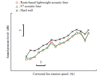
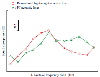
Figure 13 presents the results of the evaluation of sound absorption specifically for the broadband noise component. The sound absorption for broadband noise, shown in Fig. 13, was calculated by removing only the tonal noise from the results of the narrowband frequency analysis of the acoustic measurement data used for Fig. 11, and converting this into a 1/3-octave band frequency analysis result. The resin-based lightweight acoustic liner exhibited different sound absorption for broadband noise compared to Fig. 11, as the tonal noise component was removed. However, its maximum sound absorption was 2 dB, which was nearly the same as that of the F7 acoustic liner. It was confirmed that the resin-based lightweight acoustic liner also had a sound absorption effect for the broadband noise component.
5.4 Confirmation of structural soundness
The structural soundness of the resin-based lightweight acoustic liner during engine operation was evaluated by monitoring the dynamic strain measured using strain gauges attached on the back face of the acoustic liner. It was found that the measured strain due to vibration was significantly lower than the fatigue limit strain predicted through structural analysis. Therefore, we concluded that the resin-based lightweight acoustic liner can be mounted on engines without the risk of fatigue failure.
Additionally, after completing the engine demonstration test, various inspections were carried out to check for any changes or damage to the resin-based lightweight acoustic liner test specimen caused by its installation on the engine and exposure to engine operation. The list of inspections carried out after the completion of the engine demonstration test, along with their results, is presented in Table 2. The inspections were conducted both while the test specimen was mounted on the engine and after it was removed, it was confirmed that engine operation caused no deformation or damage to the resin-based lightweight acoustic liner, the structures fastening it to the engine components, or the engine components themselves. Therefore, the resin-based lightweight acoustic liner was mounted on the engine and the engine demonstration test was completed with it in sound condition. It was also confirmed through vibration characteristic analysis and X-ray CT scans that there were no changes caused by engine operation in the material characteristics or internal structure of the resin-based lightweight acoustic liner.

As mentioned in Section 4.1, the resin-based lightweight acoustic liner was confirmed to have the advantage of being lightweight. Based on the demonstration of the structural soundness of the resin-based lightweight acoustic liner during the engine demonstration test, it is believed that the established manufacturing technologies can produce an acoustic liner structure that is both lightweight and resistant to engine operation.
6. Conclusion
IHI has made progress in the development of the resin-based lightweight acoustic liner with the goal of applying it to high bypass ratio engines in the future and has successfully completed the engine demonstration test using the JAXA F7 engine. Acoustic measurements in the engine fan duct confirmed that the sound absorption performance of the resin-based lightweight acoustic liner was comparable to that of conventional acoustic liners. Additionally, inspections conducted after completing the engine demonstration test revealed no damage to the test specimen of the resin-based lightweight acoustic liner and no changes in its internal condition. Therefore, the resin-based lightweight acoustic liner has been confirmed to possess structural soundness across a wide range of engine operating conditions, including those equivalent to thrust at takeoff. Furthermore, the resin-based lightweight acoustic liner demonstrated its ability to be mounted on engines in the same manner as conventional acoustic liners. The demonstration results described above prove that the technologies for the resin-based lightweight acoustic liner can achieve weight reduction, sound absorption performance, structural soundness, and suitability as an engine component.
To ensure the applicability of the resin-based lightweight acoustic liner to high bypass ratio engines in the future, additional demonstrations are necessary to assess factors such as its strength against foreign object impacts and environmental resistance. These factors cannot be evaluated through the test using the JAXA F7 engine but are essential for the technical demonstration. Developing design technologies and databases is also necessary to flexibly accommodate various needs. Therefore, IHI will continue technological development in this field with the goal of applying the resin-based lightweight acoustic liner technologies to commercial products.
- — Acknowledgments —
- The development of the resin-based lightweight acoustic liner was carried out as part of a joint research project with the Japan Aerospace Exploration Agency (JAXA). The test specimen of the resin-based lightweight acoustic liner for the engine demonstration test was fabricated with the cooperation of Gifu Plastic Industry Co., Ltd. We would like to express our deep gratitude for their support.
REFERENCES
(1) International Civil Aviation Organization : Annex 16 Environmental Protection Volume I Aircraft Noise 8th Edition, 2017
(2) International Civil Aviation Organization : Report on the feasibility of a long-term aspirational goal (LTAG) for international civil aviation CO₂ emission reductions, 2022
(3) T. Hosaka, H. Nakamura, T. Oishi, M. Aotsuka, and N. Tanaka : Summary of Research and Development in the Advanced Fan Jet Research (aFJR) Project, Journal of IHI technologies, Vol. 60, No. 2, 2020, pp. 16-28 (in Japanese)
(4) R. Kagaya, et al. : Development of resin-based lightweight acoustic liner, International Gas Turbine Congress 2019 Tokyo, IGTC-2019-063, 2019
(5) R. Kagaya, et al. : Acoustic measurement for resin-based acoustic liner on turbofan engine testbed, INTER-NOISE and NOISE-CON Congress and Conference Proceedings, Vol. 268, No. 7, 2023
(6) R. Kagaya, et al. : Component-Technology Demonstration of Resin-Based Lightweight Acoustic Liner on Turbofan Engine Testbed, International Gas Turbine Congress 2023 Kyoto, IGTC-2023-169, 2023
(7) S. Tsubomoto and N. Moriwaki : Design of F7-10 High Bypass Turbofan Engine for P-1 Maritime Patrol Aircraft, Journal of IHI technologies, Vol. 57, No. 1, 2017, pp. 30-38 (in Japanese)
(8) F. Watanabe, S. Yamanaka and T. Nakamura : Demonstration Testing for 1 400ºC Class CMC Shroud with JAXA F7 Turbo Fan Engine, IHI Engineering Review, Vol. 56, No. 2, 2023
(9) MIL-STD-810C : Environmental test methods, 1975