
Development Status of Turbopumps for LE-9 Engine
MOTOMURA Taiichi, MIHARA Rei, SUZUKI Keisuke, SHIMIYA Noriyuki
MOTOMURA Taiichi : Manager, Rocket Development Department, Aero Engine, Space & Defense Business Area
MIHARA Rei : Manager, Rocket Development Department, Aero Engine, Space & Defense Business Area
SUZUKI Keisuke : Manager, Rocket Development Department, Aero Engine, Space & Defense Business Area
SHIMIYA Noriyuki : Manager, Rocket Development Department, Aero Engine, Space & Defense Business Area
LE-9 engine is the liquid oxygen/liquid hydrogen rocket engine used for the first stage of H3 Launch Vehicle, which is under the development, aimed for the entry into the satellite launch market with the strength of the high reliability and the low cost. The development of LE-9 engine is planned to achieve the final development goal concurrently with the actual operation with the provisional specification. The H3 Launch Vehicle (H3F5 : Flight No. 5) was successfully launched in February 2025, using the LE-9 engine with the provisional specification. The expander bleed cycle is applied to the LE-9 engine instead of the staged combustion cycle used in the LE-7A engine for the H-IIA Launch Vehicle, in order to reduce production costs. Furthermore, the thrust of the LE-9 engine is almost 1.4 times that of the LE-7A engine. Therefore, the design specifications of its turbopumps are widely different and the development of the turbopumps faces the various technical problems including the blade vibration. This paper describes the specifications, the technical features, and the development status of the turbopumps for LE-9 engine.
1. Introduction
The H3 Launch Vehicle is being developed to have higher reliability and launch capability and a lower cost than the H-IIA/B Launch Vehicles, which are the previous flagship rocket. Flight No. 5 was successfully launched in February 2025. Engines are important elements in the development of launch vehicles, determining reliability, performance, and cost. The H3 Launch Vehicle is equipped with the LE-9 engine as its first-stage engine. A launch vehicle engine generates thrust by pressurizing the low-pressure propellant and oxidizer supplied from tanks using turbopumps, burning them in the combustion chamber under high-temperature, high-pressure conditions, and accelerating the flow of combustion gases to supersonic speeds through a nozzle. Figure 1 shows the image of the LE-9 engine. Figure 2 shows the LE-9 engine cycle. The LE-9 engine is the world’s first high-thrust engine that uses liquid oxygen and liquid hydrogen as propellants and employs the expander bleed cycle, a simple and robust engine cycle. In this engine cycle, some of the propellant pressurized in the pump section of the turbopump cools the combustion chamber, and the heated hydrogen gas generated during this process drives the turbine and is discharged into the nozzle.
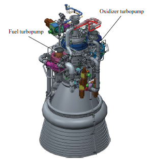
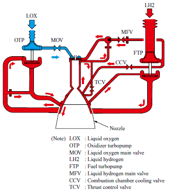
Technical issues were identified during the development of the LE-9 engine, and it took time to address them. To minimize the delay in introducing the H3 Launch Vehicle to the launch market, it was decided to bring the LE-9 engine into actual operation with provisional specifications while continuing development to achieve the final development goals. Specifically, we planned to apply the Type 1 engine with restrictions on performance and operating range to Test Flight No. 1, the Type 1A engine with no operating restrictions to initial operations, and the Type 2 engine with improved performance and reduced cost to the final mass-production-ready operations. At the time of this writing, launches up to Flight No. 5 equipped with the Type 1A engine have been completed successfully, and development of the Type 2 engine is underway.
This paper describes the design specifications of the LE-9 engine, the technical features of the turbopumps we are developing, and the progress of the ongoing development.
2. LE-9 engine overview
2.1 Engine concept
The concept of the LE-9 engine is to have low costs and high reliability(2). For this reason, the expander bleed cycle described above was adopted, eliminating the need for a combustor to drive the turbine, which was essential for the gas generator and staged combustion cycles. The engine system has been simplified, and the temperature of the turbine section, including the exhaust gas duct, has been lowered, resulting in a highly reliable, low-cost engine. However, the expander bleed cycle requires high turbine efficiency to achieve the specified power output because the temperature of its turbine drive gas is lower than that of the combustion gas. This is because, although making turbines larger and increasing drive gas rates can produce more power, the expander bleed cycle does not use the turbine drive gas for combustion, and therefore, turbine drive gas flow rates have an impact on engine performance. As for cost reduction, it is promoted by minimizing the number of parts and high-cost processes from the conceptual design stage, and applying innovative production technologies such as materials sintered by hot isostatic pressing (HIP), and additive manufacturing (AM) materials.
2.2 Engine specifications and turbopump specifications
Table 1 shows the main characteristics of the LE-9 engine. The engine thrust is 1,471 kN. The engine is characterized by the use of a simple expander bleed cycle despite its large thrust, and by the throttling capability with electric valves.
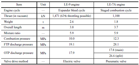
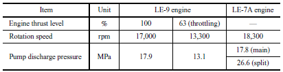
Table 2 shows the specifications of the LE-9 engine’s fuel turbopump (hereinafter referred to as “FTP”). The FTP of the LE-9 engine has a nominal rotation speed comparable to that of the LE-7A engine used for H-IIA Launch Vehicle (hereinafter referred to as “LE-7A”), but the turbine expansion ratio is very high, while the pump discharge pressure is just under 70% of that of the LE-7A.
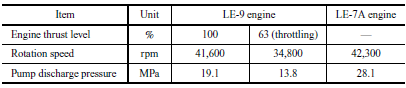
Table 3 shows the specifications of the LE-9 engine’s oxidizer turbopump (hereinafter referred to as “OTP”). The OTP of the LE-9 engine has a lower nominal rotation speed and lower turbine inlet pressure than that of the LE-7A.
3. Features of LE-9 engine turbopumps
3.1 FTP
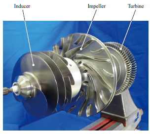
Figure 3 shows the LE-9 engine FTP rotor assembly. In the LE-7A, the pump section of the FTP consists of a single-stage inducer and a two-stage impeller, but in the LE-9 engine, the required discharge pressure was relaxed due to a change in the engine cycle, so the pump section consists of a two-stage inducer and a single-stage impeller. The single-stage impeller shortens the shaft length, enabling rated operation below the second critical speed despite high rotation speeds of over 40,000 rpm, which improves vibration stability and eliminates the need for the damper mechanism, which is required for the LE-7A. In addition, to reduce costs, relax manufacturing constraints, and ensure sufficient structural strength, an open impeller without a shroud is adopted. In addition, hybrid ceramic bearings are used to improve pump efficiency by reducing bearing cooling flow, and a two-stage supersonic impulse turbine with an increased turbine expansion ratio is used to increase the output from the low enthalpy turbine driving gas.
3.2 OTP
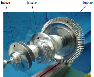
Figure 4 shows the LE-9 engine OTP rotor assembly. The OTP turbine is a two-stage transonic reaction turbine with a low inlet pressure. To achieve a large output, the peripheral speed and nozzle area must be designed to be large, and therefore, the turbopump has a turbine disk with a huge diameter. On the other hand, since the first critical speed of the OTP is a vibration mode in which the turbine whirls, the shaft diameter of the OTP is increased, and a rigid rotor configuration is adopted to allow steady-state operation below the first critical speed. Technical issues, including the need to increase the bearing diameter due to increased shaft diameter, have been resolved through element tests.
3.3 Cost reduction
From the conceptual design stage, cost reduction ideas were extracted from all areas, including (1) reducing the number of parts, (2) changing processing methods, (3) changing or eliminating special processes, (4) changing materials, and (5) changing or eliminating assembly processes, and then the feasibility of each idea was examined. Unlike the LE-7A, the LE-9 does not have a secondary combustor. This results in a low turbopump discharge pressure, which allows the number of parts to be reduced by using a single-stage impeller. Lowering the temperature of the turbine drive gas also allows for cost reductions by using low-cost turbine materials and blisks which are turbine disks with blades integrated and by reducing the number of surface treatment points. Open impellers without shrouds are used for both the FTP and OTP to improve machinability and reduce cost.
4. LE-9 engine turbopump cold flow test
4.1 Purpose of test
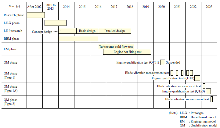
Figure 5 shows the development schedule for the LE-9 engine. After element-level tests were conducted from 2014 to confirm the function and performance of each element, engineering models of the turbopumps were manufactured starting in FY2016, and a cold flow test was conducted for the first turbopumps at the end of FY2016. The purpose of the turbopump cold flow tests was to understand the following cold flow characteristics of the turbopumps before the engine hot firing test, to reduce risk, and confirm that the required performance was achieved.
- Turbopump performance characteristics (pump, turbine)
- Shaft vibration characteristics (axial, radial)
- Mechanical system characteristics (bearings, shaft seals)
- Internal circulation characteristics
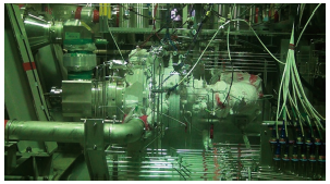
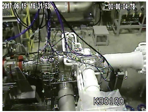
The tests were conducted at the Japan Aerospace Exploration Agency (JAXA) Kakuda Space Center (Miyagi Prefecture). Figure 6 shows the LE-9 engine FTP cold flow test, and Fig. 7 shows the LE-9 engine OTP cold flow test.
4.2 Test results
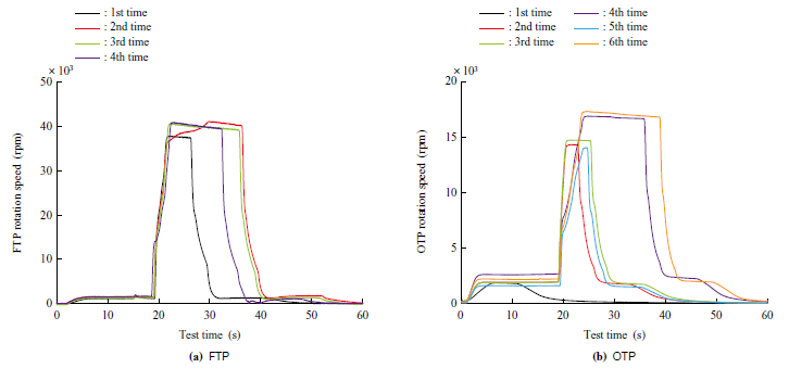
Figure 8 shows an example of the cold flow test data for the LE-9 engine turbopumps. To obtain data, the turbopumps were operated by supplying GH2 (hydrogen gas) from a pressurized gas reservoir to the turbine and supplying LH2 (liquid hydrogen) or LOX (liquid oxygen) from a run tank. There were no problems with the start-up/shutdown transient characteristics, the characteristics of both FTP and OTP during steady-state operation almost satisfied the design predictions, and no excessive shaft vibration occurred. However, after the test, a problem was found in the turbine section of the OTP, and to solve the technical issue, the component configurations of both the FTP and OTP were modified, and the tests were continued. At the time of this writing, FTP has been tested a total of 26 times for 565 s, and the OTP, a total of 23 times for 459 s.
4.3 Blade vibration measurement
In developing the LE-9 turbopumps, a blisk configuration was adopted for the turbine sections of both the FTP and OTP to achieve high efficiency and low cost. However, the problem of fatigue arose due to flutter and resonance. In order to modify the design to solve the problem, it was necessary to understand the blade vibration status. Therefore, the blade vibration of the blisk was measured during operation.
Blade vibration measurement was carried out using the following two methods.
- Detect the vibration status of all blade tips using multiple optical sensors mounted on the outer circumference of the rotor blades
- Measure strain using a telemetry method in which the data measured by a small strain gauge attached to the blisk is transmitted from a transmitter attached to the rotor to a receiver attached to the casing
Both methods have been proven in jet engine development. However, the LE-9 turbopumps are driven by the turbines using hydrogen gas, the test article and measurement equipment are cooled by heat transfer from the cryogenic fluid (liquid hydrogen or liquid oxygen) on the pump side before operation, and they operate at speeds exceeding as high as 40,000 rpm. Therefore, the environment in which the equipment and sensors are used differs significantly from that for jet engines. To minimize the measurement risk in such an environment, the first blade vibration measurements were performed in a turbopump cold flow test after the necessary element tests were conducted. As a result, the necessary specifications and procedures for acquiring the data were successfully established. However, it was found that there was a greater variety of blade vibrations than estimated. Therefore, it was decided to mainly use (2) the telemetry method for strain measurements, which is less dependent on the mode shape.
Establishing a blade vibration measurement method for turbine blades of launch vehicle turbopumps has enabled us to examine effective countermeasures against blade vibration problems by accurately identifying their causes.
5. LE-9 engine hot firing test
5.1 Test overview
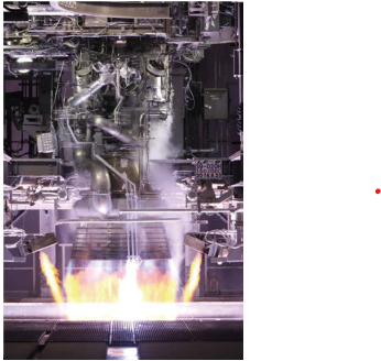
Engineering models, for which the turbopump cold flow test had been completed, were incorporated into the engine system, and to obtain the following characteristics, it was subjected to hot firing tests as the first unit at the JAXA Tanegashima Space Center (Kagoshima Prefecture) from April 2017. Figure 9 shows the LE-9 engine hot firing test.
- Confirm the steady-state performance
- Establish the start-up, shutdown, and throttling sequences
- Confirm the transient characteristics
- Grasp turbopump suction performance and dynamic characteristics
- Grasp operating point control characteristics using an electric valve
- Grasp pre-cooling characteristics
5.2 Test results
During the engine hot firing tests, both the FTP and OTP operated properly, including start-up/shutdown transient behavior, and no excessive shaft vibration occurred. The pump’s suction performance exceeded the target, and it was confirmed that there were no harmful vibrations. The turbine sections of the FTP and OTP had problems such as fatigue due to flutter and resonance, but for both, the turbine design was modified to continue engine hot firing tests, and it was confirmed that the technical issues, mainly blade vibration, had been resolved.
Since then, 120 tests totaling 16,049 s have been conducted at the time of this writing, including rocket system tests, such as battleship firing tests and captive firing tests, and qualification tests for the Type 1 and Type 1A engines.
Figure 10 shows an example of the operating data from engine hot firing tests conducted to date. In these tests, the response of each blade vibration mode was measured by accelerating and decelerating up to the maximum speed under two different conditions.
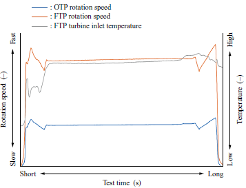
The qualification tests of the Type 1 and Type 1A engines have already been completed, and the operational flight up to Flight No. 5 equipped with the Type 1A engine has also been completed without any problems.
In the future, we plan to conduct qualification tests on the Type 2 engine, whose design has been modified to further improve performance and reduce costs, to verify its feasibility and durability over the operating range.
5.3 Blade vibration measurement
To verify the effects of the blade vibration countermeasures under actual operating conditions, turbine blade vibrations were measured in engine hot firing tests as well. Since engine hot firing tests can be performed longer than turbopump cold flow tests, they can be performed while changing operating conditions. Therefore, we successfully obtained more detailed data that was able to be reflected in the design.
6. Conclusion
The above is an overview of the development of the LE-9 engine, engine design specifications, technical characteristics of the turbopumps, and the progress of the development of the turbopumps. The LE-9 engine is a high-thrust engine unprecedented in the world, applying the expander bleed cycle. It also applies innovative production technologies and strives for thorough cost reduction.
As for the H3 Launch Vehicle, after the failed launch of Test Flight No. 1, Test Flight No. 2 to Flight No. 5 have been successfully launched. The LE-9 engines have operated properly in all these cases and are now in the initial operational phase with provisional specifications.
As for the technical issues identified during the development of the LE-9 engine, including blade vibration, turbopump cold flow tests and engine hot firing tests have been conducted to investigate the causes and verify the effects of countermeasures. In particular, we have received high praise from outside the company, including the Turbomachinery Society of Japan’s Technology Award for the blade vibration countermeasures based on measurements of turbine blade vibration during operation.
We plan to continue manufacturing the Type 1A engine for initial operation and conduct development tests on the Type 2 engine, a low-cost, mass-production-ready engine.
This project is being carried out based on a development contract with the Japan Aerospace Exploration Agency (JAXA).
- — Acknowledgments —
- We would like to express our deepest gratitude to all relevant parties, including the Japan Aerospace Exploration Agency, Mitsubishi Heavy Industries, Ltd., and Waseda University, from whom we received significant support and cooperation in developing the turbopumps for the LE-9 engine. Finally, we would like to express our gratitude to Mr. Tsutomu Mizuno and Mr. Hisayuki Motoi, who regrettably passed away before the completion of the development, leaving behind many achievements.
REFERENCES
(1) N. Negoro, T. Tamura, H. Manako, T. Onga, T. Kobayashi and K. Okita : Overview of LE-9 Engine Development for H3 Launch Vehicle, 67th International Astronautical Congress, 2016
(2) N. Azuma, Y. Ogawa, K. Aoki, T. Kobayashi, K. Okita, T. Mizuno, K. Niiyama and N. Shimiya : Development Status of LE-9 Engine Turbopumps, 53rd AIAA/SAE/ASME/ASEE Joint Propulsion Conference, 2017
(3) T. Mizuno, H. Oguchi, K. Niiyama and N. Shimiya : Development of Turbopump for LE-9 Engine, IHI Engineering Review, Vol. 51, No. 2, 2018
(4) H. Kawashima, A. Kurosu and T. Kobayashi : Qualification test results of LE-9 engine for H3 launch vehicle, 74th International Astronautical Congress, 2023