
Development of the Ground Evaluation Model for an Integrated Power Generation and Transmission Panel Aimed at Space Solar Power Systems
OGAWA Akihito, TANAKA Naohiro, OZAWA Yuichiro

OGAWA Akihito : Electronics Technologies Group, Technologies Development Department, IHI Aerospace Co., Ltd.
TANAKA Naohiro : Manager, Electronics Technologies Group, Technologies Development Department, IHI Aerospace Co., Ltd.
OZAWA Yuichiro : Manager, Space Systems Business Development Office, Aero Engine, Space & Defense Business Area
Research on Space Solar Power Systems (SSPS), which generate solar power without emitting greenhouse gases in space unaffected by weather or the day-night cycle and transmit the generated electricity wirelessly to the Earth, enabling stable and clean power, is being actively pursued worldwide. IHI Aerospace Co., Ltd. has been continuously engaged in research and development aimed at realizing SSPS since the early stages of R&D in Japan. As part of these efforts, we developed and evaluated a ground test operational model of a power generation and transmission panel, intended for Low Earth Orbit (LEO) space demonstration, which is the next step following ground-based demonstrations. We have confirmed that the model achieves the desired functionality and performance. This accomplishment contributes to advancing the phase towards the development of a space demonstration device.
1. Introduction
Space Solar Power Systems (SSPS), first proposed in the United States in the 1960s, have since been the subject of research around the world with the aim of their realization. In Japan, the development and promotion of SSPS have been outlined in the Basic Plan on Space Policy as a potential solution to energy, climate change, environmental, and other related issues(1). Active research and development of SSPS continue at universities, research institutions and private companies(2).
IHI Aerospace Co., Ltd. (IA) continues its research and development of SSPS, focusing on wireless power transmission and reception technologies. This includes the development of receiving units for long-distance power transmission and reception demonstration, as well as receiving units for drone-mounted applications. Figure 1 shows the receiving unit for long-distance power transmission and reception demonstration.
Since the proposal of SSPS, many research projects have been launched, and a variety of models have been proposed(4). One of the models proposed in Japan is the USEF model(5), presented by the Institute for Unmanned Space Experiment Free Flyer (USEF) in 2006.
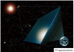
The USEF model proposes that a power generation and transmission site in space can be constructed by arranging a large number of integrated power generation and transmission panels, all with identical specifications. Figure 2 shows an illustration of the USEF model. The development of integrated power generation and transmission panels that meet the required specifications is directly linked to the realization of SSPS in the future.
Efforts to develop the USEF model have continued even after the reorganization of USEF into Japan Space Systems (J-spacesystems). Currently, research and development are progressing as part of the “Research and Development Project for the Efficiency Improvement of Wireless Power Transmission and Reception Technology in Space Solar Power Systems,” commissioned by the Ministry of Economy, Trade and Industry.
This project involves the prototype development of an operational ground evaluation model as part of the feasibility study of integrated power generation and transmission panels in space. IA has taken the lead in developing the ground evaluation model. One of the goals of the project is the preliminary verification for the space demonstration test of the integrated power generation and transmission panels, which is planned for the next development phase(6).
This paper reports the specifications of the prototype ground evaluation model, as well as the details and results of the verification test conducted during its development.
2. Ground evaluation model of integrated power generation and transmission panel
2.1 Positioning of development
The development of the ground evaluation model is positioned as one of the final steps in the roadmap toward the realization of SSPS, prior to transitioning to space-based demonstrations in the future.
The purposes of the development are to confirm the feasibility of the USEF model by creating a ground evaluation model that incorporates the power generation and transmission functions into a unit with dimensions of approximately 500 × 500 mm, the target size of the practical USEF model, and to identify future development challenges. Prior to this development, there were reports on the development of partial models(7). However, this development marks the first attempt to create a complete panel that incorporates the required functions within the target dimensions.
In addition to the above purposes, the ground evaluation model was expected to be used in the outdoor power transmission and reception demonstration planned as part of the exhibition of achievements from the SSPS project. Therefore, the development of the ground evaluation model was carried out with consideration for its operability in outdoor power transmission.
2.2 Targeted specifications
As described in Section 2.1, the ground evaluation model was required to include both power generation and power transmission functions, as required for the operational panels to be mounted on the USEF model. The following functions are required for the ground evaluation model, identified through the analysis of its operational concept.
- (1)Power generation function
- In the USEF model, the integrated power generation and transmission panels perform various operations using the power generated from sunlight. Additionally, each panel is designed to face the Earth through passive attitude control using gravity, and does not have any mechanism for tracking the direction of the Sun.
Based on the above, a triple-junction solar cell, capable of achieving the required power generation as the power generation function, is arranged on the primary surface oriented toward the Sun. Additionally, the function includes the generation of wireless power and the high-efficiency distribution of this power to the internal panel equipment required for executing internal control. The triple-junction solar cell is formed by stacking three different types of semiconductors to expand the wavelength range of sunlight, enabling highly efficient conversion of sunlight into power. - (2)RF power transmission function (wireless power transmission)
- In the USEF model, wireless power transmission to the ground is performed by generating and amplifying a radio frequency (RF) signal, which serves as the reference signal for generating microwaves from the power generated by the solar cells, in the integrated power generation and transmission panel. The signal is emitted toward the Earth through an antenna.
Based on the above, one of the definitions of the RF power transmission function is to generate and amplify an RF signal using the power generated by the power generation function, and to enable the signal to be radiated externally as radio waves through the antenna mounted on the model. - (3)RF power transmission function (beam direction control)
- SSPS requires precise control of the power transmission direction to achieve wireless power transmission from space (the geostationary orbit at an altitude of approximately 36,000 km in the case of the USEF model) to a power receiving site on the ground with a diameter of several kilometers.
In response to this requirement, the USEF model is designed to use a large-scale phased array antenna formed from a large array of integrated power generation and transmission panels.
A phased array is a technology that electrically controls the power transmission direction by controlling the electrical phase of each input signal through feed points distributed across the antenna. By increasing the scale of the phased array, improvements in pointing accuracy and resolution are expected.
Based on this, another definition of the RF power transmission function is to have multiple RF signal output channels that are capable of phase control, enabling electrical control of the power transmission direction.
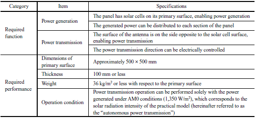
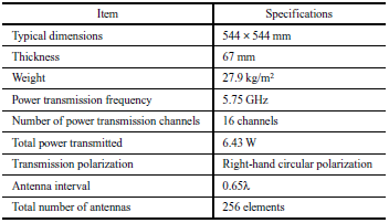
In addition to the above functional requirements, the specifications for the ground evaluation model include the dimensional requirements (approximately 500 × 500 mm with a thickness of 100 mm or less), as stipulated in the project goals, and the ability to perform wireless power transmission and internal control using only the power generated by its own power source. The targeted specifications are listed in Table 1.
2.3 Component configuration
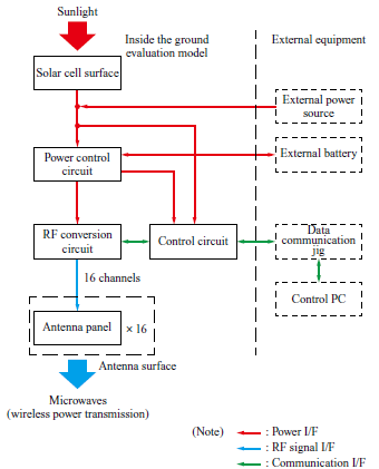
Based on the target specifications outlined in Section 2.2, the component configuration is shown in Fig. 3. With this configuration, the operational flow from the arrival of sunlight to wireless power transmission is summarized below.
- (1)Power generation operation
- Power is generated by the sunlight incident on the solar cell surface, and the generated power is supplied to the control and RF circuits via the power control circuit.
The ground evaluation model is configured to support battery connections, in line with the requirements for the USEF model, which is expected to operate in geostationary orbit. When the ground evaluation model is connected to a battery, the maximum power point tracking (MPPT) control becomes active, allowing the solar cells to maintain the most efficient operating point to maximize power generation based on the incident light intensity at any given time. - (2)RF signal conversion operation
- Based on the power supplied from the power control circuit, the RF circuit generates an RF signal at the power transmission frequency of 5.75 GHz. The circuit also splits the generated RF signal into branches corresponding to the number of output channels and performs electronic control of the amplitude and phase for each channel.
The number of output channels for the ground evaluation model was set to 16 in accordance with the specifications of the USEF model. This configuration is designed for beam direction control using the phased array and serves to compensate for the offset (such as fixed delays and differences in amplification characteristics) of the RF signal for each channel. - (3)Amplification and antenna radiation
- After the amplitude and phase of the RF signal output from the RF circuit are controlled, the RF signal is input to an amplifier and then radiated toward the target from the antenna surface.
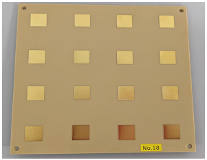
As described in (2), the ground evaluation model has 16 channels, and accordingly, it is equipped with 16 antenna panels (subarray antennas) with identical specifications. The number of antenna elements (patch antennas) in each antenna panel was also set to 16, in accordance with the USEF model.
Accordingly, the RF signal is split twice into 16 branches: once within the RF conversion circuit to supply power to the 16 antenna panels, and once within each antenna panel to feed the antenna elements. The antenna panels do not contain active components, so power is supplied to the antenna elements via common mode feeding. Therefore, control of amplitude and phase is performed only in the former split.
2.4 Prototype specifications
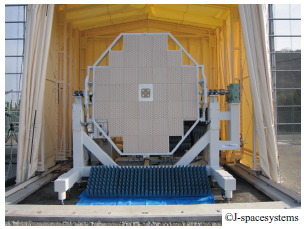
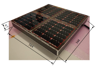
A prototype of the ground evaluation model was developed based on Sections 2.2 and 2.3. Table 2 lists the representative specifications of the ground evaluation model, and Fig. 4 shows its exterior as photographed from the solar cell side. The ground evaluation model also has an antenna surface on the side opposite the solar cell surface, which, as described in Section 2.3 (3), is composed of 16 antenna panels. Figure 5 shows the exterior of an individual antenna panel.
3. Verification test
3.1 Overview
A verification test was conducted to verify that the developed ground evaluation model possesses the targeted functions and performance. The verification test consisted of the following three items: (1) verification of the power generation function; (2) verification of the RF power transmission function; and (3) verification of the autonomous power transmission control.
When the 16 antenna panels are regarded as a single antenna surface, the ground evaluation model has a relatively large antenna aperture, resulting in a long far-field distance required for measurement. Therefore, for evaluations involving power transmission operation, a test site that allows for a long line-of-sight distance is desirable. Based on this, the evaluation was conducted using the large anechoic chamber A-METLAB (Advanced Microwave Energy Transmission LABoratory), owned by Kyoto University.
3.2 Test procedure
3.2.1 Verification of power generation function
The power generation function of the ground evaluation model was verified in the outdoor area in front of A-METLAB under natural sunlight.
Figure 6 shows a photograph of the exterior taken during the verification. During the measurement, the actual power generation output of the ground evaluation model, recorded as housekeeping data (hereinafter referred to as the “HK data”), was compared with the theoretical power generation output calculated from the measurements of a solar radiation meter.
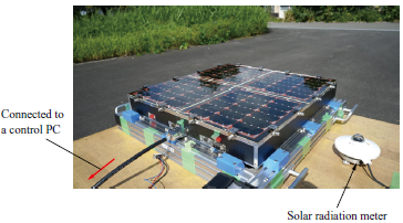
The ground evaluation model performed power generation while connected to an external battery with sufficient (chargeable) capacity. Since MPPT control was enabled under these conditions, the solar cells were expected to operate at maximum efficiency. In calculating the theoretical power generation output, it was assumed that MPPT control was active and the solar cells operated at maximum efficiency, with consideration also given to the Sun’s inclination angle (i.e., the angle of incidence on the power generation surface).
3.2.2 Verification of the RF power transmission function
The verification of the RF power transmission function was based on the following two criteria: (1) the ability to receive the expected power in the forward direction as predicted by the link budget calculation, and (2) the correct formation of the boresight (the direction of maximum antenna gain) of the beam pattern in the intended radiation direction.
Figure 7 shows the configuration of the evaluation system constructed inside A-METLAB. Since the test was conducted in an anechoic chamber, the ground evaluation model was connected to a stabilized power supply as its power source and mounted on a stand (hereinafter referred to as the “vertical installation jig”) to enable radio waves to be radiated in the horizontal direction. Figure 8 shows an external view of the model in its mounted state.
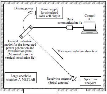
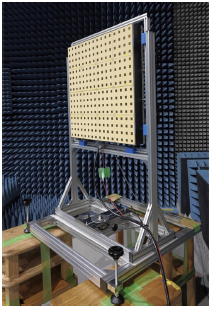
Additionally, a spiral antenna with a known antenna gain was prepared as the receiving side, and a spectrum analyzer was used to monitor the power received at the transmission frequency.
Since the vertical installation jig is equipped with a horizontal rotation mechanism, the beam pattern was measured by physically rotating the jig after setting the intended radiation direction of the ground evaluation model.
Prior to the evaluation of the RF power transmission function, in-phase adjustment (transmission system calibration) of the 16 output channels of the ground evaluation model was carried out. Specifically, based on the configuration shown in Fig. 7, the calibration was performed by adjusting the phase shift of 15 of the 16 RF output channels, using one channel as a reference, so that the power received at the receiving antenna was maximized.
3.2.3 Verification of autonomous power transmission control
The verification of the autonomous power transmission control was also conducted in A-METLAB. Since the evaluation was conducted indoors, a solar cell simulator (Agilent E7405A) capable of reproducing the specified output characteristics of the solar cells was used to simulate solar power generation. The evaluation setup was based on the configuration shown in Fig. 7, except that a solar cell simulator is connected instead of the stabilized power supply.
This verification was conducted using solar radiation intensity as a test condition, and the feasibility of power transmission was confirmed based on the power received by the receiving system. The solar radiation intensity was simulated by inputting the characteristics (V-I curve) of the solar cells used in the ground evaluation model into the solar cell simulator.
The characteristics input into the solar cell simulator were based on parameters provided by the solar cell manufacturer. Since the values provided by the manufacturer were only for AM0 conditions, parameters for other solar radiation intensity conditions were set by assuming a linear decrease in current with respect to solar radiation intensity, while maintaining the voltage characteristics.
In this evaluation, external batteries were not used, as only the amount of power equivalent to that generated by the solar cells was supplied to the ground evaluation model. Therefore, the MPPT control was not active during the evaluation, and only the amount of power corresponding to the internal consumption of the ground evaluation model was drawn from the solar cell simulator.
4. Verification test results
4.1 Verification results of power generation Function
The verification was conducted outdoors under weather conditions selected for having relatively few clouds. Based on the HK data of the ground evaluation model during the verification period, it was confirmed that continuous power generation was carried out using sunlight and that surplus power was being stored in the batteries.
Additionally, it was confirmed that until the batteries became fully charged, the amount of power generated was nearly equal to the theoretical value, and that after full charge, the power generation was suppressed to a level equivalent to the internal power consumption.
4.2 Verification results of the RF power transmission function
The test results are organized according to the two criteria outlined in Subsection 3.2.2. Table 3 compares the power received on the receiving side, showing a comparison between the theoretical values obtained from the link budget calculation and the actual measured values. As a result, it was confirmed that the power expected from the link budget calculation was able to be received in the forward direction.
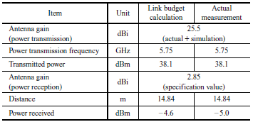
Figure 9 illustrates power levels, with the horizontal axis representing the horizontal angle relative to the antenna surface of the ground evaluation model, and the vertical axis showing the power level referenced to peak power. This shows that the boresight of the beam pattern is correctly formed in the intended radiation direction. In the legend of Fig. 9, the simulated values represent the simulation results of the composite pattern based on the pattern measured from an individual antenna panel, while the measurement results represent the actual measurements obtained using A-METLAB.
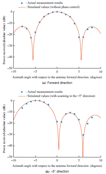
The graph shows two cases: one with the beam directed towards the forward direction (0°), and the other with the beam directed towards the −5° direction. The evaluation results show a slight deviation in the beam center direction (boresight), particularly in the case of the −5° beam direction; however, the actual measurement results still correspond well with the theoretical values.
4.3 Verification of autonomous power transmission control
Verification of the availability of autonomous power transmission with respect to incident light intensity was conducted by changing the power input conditions from the solar cell simulator. Table 4 shows the verification results. In the evaluation test, power transmission was conducted in two scenarios: one where solar radiation intensity was gradually reduced from the AM0 condition (1,350 W/m2) (Cases 1 to 4), and another where transmission was initiated from the OFF state under a fixed solar radiation intensity (Cases 5 and 6).
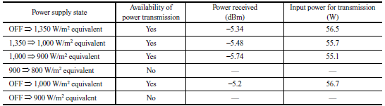
The verification results confirmed that autonomous power transmission is possible under the AM0 condition. Additionally, the results from Cases 5 and 6 confirmed that the threshold for initiating power transmission lies between 900 and 1,000 W/m2, while the results from Cases 1 to 4 confirmed that the threshold for continuing power transmission lies between 800 and 900 W/m2.
5. Discussions
5.1 Power generation function
As described in Section 4.1, the verification results confirmed that the ground evaluation model can generate power from sunlight, properly charge the batteries, and switch the solar cell control method when the batteries are fully charged (from MPPT control to constant power generation control).
The function and performance of the solar panels were confirmed during the inspection conducted after their assembly, while the function and performance of the MPPT control circuit were verified in tests conducted on the individual substrate. The results of this power generation function verification are consistent with the inspection and test results of the components, leading to the conclusion that the power generation function of the ground evaluation model is sound.
5.2 RF power transmission function
- (1)Availability of power transmission
- As shown in Table 3, the power received in the forward direction after calibration exhibits a difference of approximately 0.4 dB between the actual measurements and the theoretical values. Considering that an error of approximately 1 dB is highly likely due to the radio wave environment of the measurement system and the interior of the anechoic chamber, it can be concluded that power equivalent to that expected from the link budget calculation was successfully received.
Therefore, it was determined that power transmission can be carried out as designed. - (2)Availability of electrical control of power transmission direction
- Although there is a slight deviation in the boresight direction due to alignment errors in the mechanical system, the beam pattern closely matches the simulation results, as shown in Fig. 9.
Therefore, it is thought that the beam pattern has formed as expected, and the boresight is correctly aligned with the intended direction. Based on the above, it was concluded that the power transmission direction could be electrically controlled.
5.3 Autonomous power transmission control
As described in Section 4.3, the ground evaluation model is capable of autonomous power transmission under AM0 conditions. Additionally, the thresholds for initiating and continuing power transmission were identified to be between 900 and 1,000 W/m2, and between 800 and 900 W/m2, respectively.
The higher threshold for initiating power transmission, compared to the threshold for continuing transmission, is considered to be due to the RF circuitry (such as the amplifier) inside the panel temporarily requiring a large inrush current when power transmission is initiated.
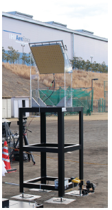
After the evaluation test at A-METLAB, the ground evaluation model was used in an outdoor power transmission and reception demonstration (SSPS demonstration) and successfully performed autonomous power transmission using natural sunlight(8). Figure 10 shows the external appearance of the ground evaluation model used in the demonstration, while Fig. 11 illustrates an example of the variation in solar radiation intensity during power transmission operation.
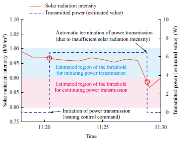
The two red circles in Fig. 11 indicate the solar radiation intensity at the time of power transmission initiation and termination. The figure also shows shaded areas that correspond to the ranges of solar radiation intensity for the thresholds of initiating and continuing power transmission, which were confirmed from the evaluation results. Both red circles are within the respective shaded areas.
As a result, the outdoor power transmission and reception demonstration using the RF power transmission function validated the accuracy of the autonomous power transmission control verification results from A-METLAB.
6. Conclusion
The ground evaluation model of the integrated power generation and transmission panels was developed as a component of the USEF model proposed for future SSPS applications.
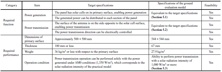
Additionally, a verification test was conducted to confirm whether the target set during the design phase could be achieved. As summarized in Table 5, the verification results show that all the goals were achieved, completing the preparation for the Low Earth Orbit space demonstration.
In the future, IA will continue to contribute to the realization of SSPS by leveraging the insights gained through this development.
- — Acknowledgments —
In this development, IA participated in the design, fabrication, and testing of the ground evaluation model for the integrated power generation and transmission panels as part of the “Research and Development Project for the Efficiency Improvement of Wireless Power Transmission and Reception Technology in Space Solar Power Systems” implemented by Japan Space Systems. We would like to express our profound gratitude to all the personnel from Panasonic System Networks R&D Lab. Co., Ltd. and other organizations who contributed to this development.
Additionally, we would like to express our gratitude to the members of the Shinohara Laboratory at Kyoto University for their valuable assistance during the evaluation tests conducted using A-METLAB.
REFERENCES
(1) Cabinet Office : Basic Plan on Space Policy, https://www8.cao.go.jp/space/plan/plan2/kaitei_fy05/honbun_fy05.pdf, accessed 2024-08-30 (in Japanese)
(2) Japan Space Systems : Current Situation of Research and Development Toward the Realization of Space Solar Power Systems (SSPS), https://www.jspacesystems.or.jp/jss/files/2023/08/ISTS2023_SSPS.pdf, accessed 2024-08-30 (in Japanese)
(3) Y. Ozawa, T. Fujiwara, N. Tanaka, K, Sasaki and S. Nakamura : Development of Receiving Section of Microwave Power Transmission Test Model, IEICE Transactions on Communications, Vol. J99-B, No. 11, 2016, pp. 1,030-1,040 (in Japanese)
(4) N. Shinohara : Solar Power Satellite/Station, the Institute of Electronics, Information and Communication Engineers, Ohmsha, 2012, pp. 7-21 (in Japanese)
(5) Institute for Unmanned Space Experiment Free Flyer : Investigation Report on Solar Power Utilization Promotion Technologies, 2008 (in Japanese)
(6) Japan Space Systems : Roadmap for the Research and Development of the 2006 Model Integrated Power Generation and Transmission System, https://www.jspacesystems.or.jp/jss/files/2021/07/SSPS_H28_Roadmap_a.pdf, accessed 2024-08-30 (in Japanese)
(7) N. Adachi, D. Joudoi and K. Makino : Prototype Testing of Panel for Power Generator and Microwave Transmitter used in Space Solar Power Systems, IEICE Technical Report, Vol. 113, No. 88, 2013, pp. 57-61 (in Japanese)
(8) Japan Space Systems : Demonstration Test of Space Solar Power Systems (SSPS), https://www.youtube.com/watch?v=iGjh9w-4uf0&t=95s, accessed 2024-10-11 (in Japanese)